ANALYSIS of COMPONENTS:
This analysis is based upon my observations and conclusions pertaining to the first manufactured plane (the Number 4) and is usually relevant to the other numbered bench planes, although these latter planes will definitely show some various differences and therefore those sections should be read for a more accurate analysis.
PAINTED FINISH
The finish on these planes is most variable, going from almost what I consider to be careless, to what is simply superb (rare).
The basic paint colour stayed almost the same throughout production (a royal blue with a hint of red), but was surface treated differently as time progressed. The first planes appear to have had a good base colour coat applied and this has survived well. but slightly later planes had a light varnish applied over the finish, and this varnish has darkened with age, dried out and therefore has left an ‘alligatored’ or ‘crazed’ finish appearance, which makes the plane now looking very cheap.
The care with which the paint was applied was variable, with mating surfaces of mouth, frog and body being either partially painted (later examples) or well delineated. Later, towards the middle of this company’s existence, the finish took on an almost ‘porcelain’ type quality which was very smooth, shiny and more scratch resistant. (See photo below on the Right) The surface quality of these ‘porcelain‘ planes is second to none at the comparable price range, (which seems to have always been very competitive) and they remain as pristine today as they were 60 years ago. This finish far surpasses any that I have seen produced by RECORD, STANLEY or the WODEN planes of that time (and I have collections of all 3 of these makes to compare )….it seems to be almost ‘fired on’ and I wish I could find more.
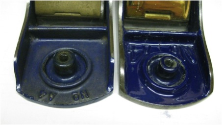
The above photo shows the ‘porcelain’ finish on the right and the over varnished finish on the left, showing ‘browning’ of the varnish. Remember that the first No.4 planes (numbered simply No 4) generally do not have the varnish top coat, and therefore have a much cleaner look to them. Only early planes had a painted finish to the front edge (see BM1 and BM2 below) .
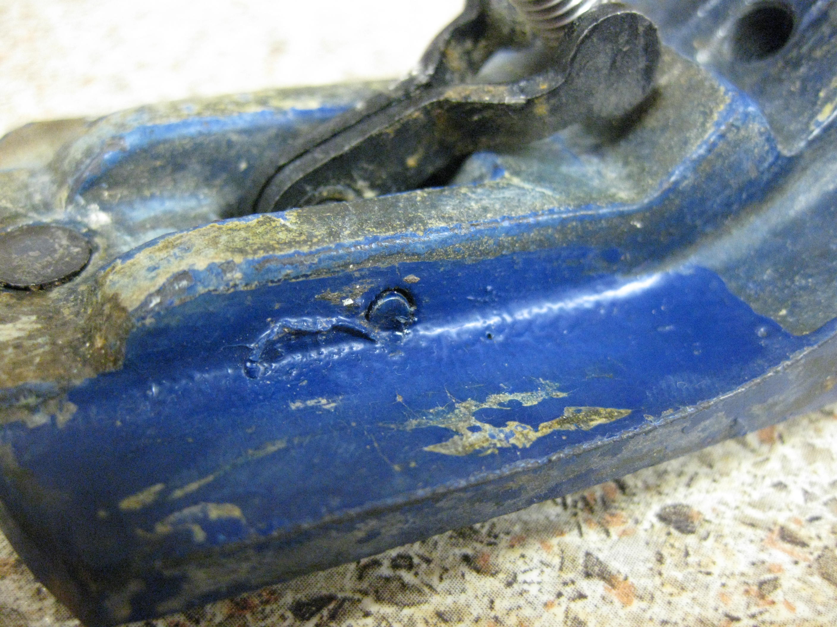
I have also noted that many planes may have been painted, varnished, AND THEN maybe hand spot-painted by the manufacturer, in order to fill in any obvious errors in the original finish. I have many examples that show that the Frog must have been first painted and varnished, the hole for the Stirrup pivot rod bored, and after that the hand assembly was completed. That area then seems to have been hand spot painted to cover up the marks left by the hand assembly, as shown below.
If the Frogs were varnished/shellacked it would appear that this application was only applied to the lower face and edges of the Frog, as no such top surface application has been observed.
As a point of interest, I have an A6 ‘Porcelain’ plane with an F2(Ogee) frog that shows a large amount of gathered paint on the edges of the top surface. I have therefore deduced that the raw casting was finished and the top surface spray painted. The top surface was then ‘sanded’ smooth (leaving required paint in the lowered panels) and then the bottom surface had paint applied. But any excess paint that dripped down from this spraying onto the working top surface was not later removed. This obvious lack of quality control caused the blade that mates with this surface to not run with full surface contact.
SIDES & BOTTOM FINISH
The planes seem to have been ‘squared’ to the sole by a surface machining method [as opposed to the cheaper method employed universally today of ‘ belt sanding’], and the original swirls can be seen on the sides and bottom. But it should be noted that there was no consistent way that the planes were ground, because I have swirl patterns going in different directions on different planes.
Unfortunately, (and please do not do this !) many of today’s owners want to have a nice smooth look to their planes and have spent a lot of time irradicating these beautiful manufacturing marks. It is therefore hard to know now, because of the presence of these ‘conditioned’ planes, whether the grind marks were originally always present. My later examples all show no such marks [or at the least a very fine grind pattern] so it is difficult to deduce when the transition may have occurred in the production methods between coarse machined marks and the later smoother ‘ground’ surface.
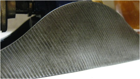
This is what I like to see, exactly as it came from the factory.
WOOD
The woods used for the Handles and Knobs were usually either Beech or Maple, and since WS was a British firm, European Beech and Sycamore (Maple) are probably more accurate terms. It is hard to determine which wood was used first in production, but I think that it was Maple as these examples are not seen at all after the first ‘Types’.
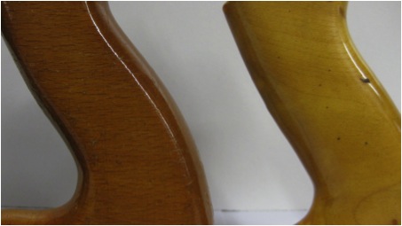
I have usually only seen Beech used for the rear Handles, with only a few of Maple, and of these planes very few have Maple front knobs. This wood is a finer grained, smoother finishing wood than Beech and retains a finished lighter colour than the more orange toned Beech. The later wooden parts were always varnished quite thickly, with the varnish applied being ‘ light toned’ early on and getting more ‘orange coloured ‘in the middle to late production models. (See photo of Rear Handles in that section below)
The Maple handle (shown below on the right ) is silky smooth and is wonderful to hold, and unlike the Beech, seems to hold the varnish well. I have many WS and WODEN Beech handles that have suffered widespread surface cracking and delamination of the varnish due to fluctuating humidity levels. But this does not appear to happen with the WS Maple handles, which are mostly as pristine today as the day when they were sprayed. [They must have been sprayed because the bolt shaft down the middle of the handle shows no varnish invasion, as would have be seen in a dipping process].
The picture below shows the more grainy and orange toned Beech on the left.
 Beech Maple
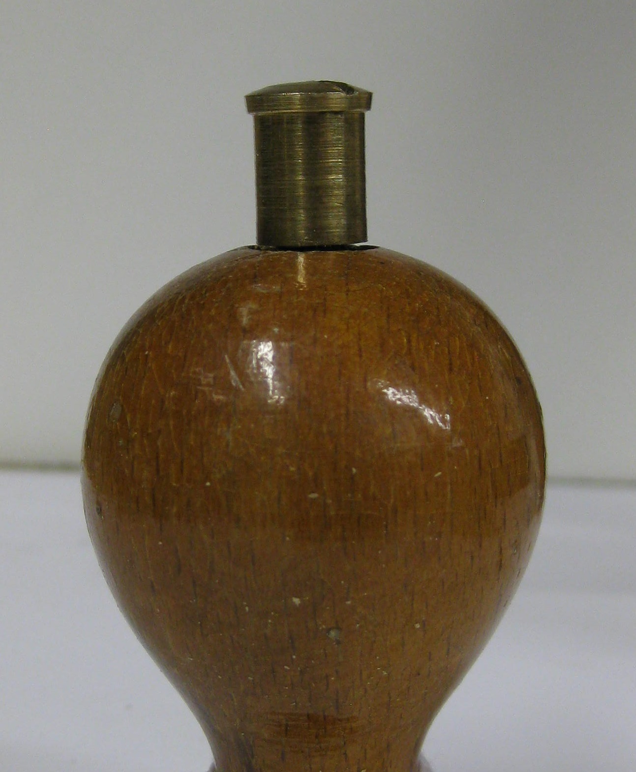
FRONT KNOBS
I have found only 3 distinctive styles of front knobs, progressing from a slim shapeless first version (K1), through a more rounded form (K2)and then to the last form (K3), which has a very round shape, a slim neck and a distinct slanted lower area. Distinguishing between K1 and K2 can be tricky. The difference is really in a slightly more swollen appearance to the top of the knob. There was a great variation in both the neck diameter and the equator of the round knob of K1, and as far as I can measure, the equator diameter of K1 is a maximum of 37mm and the neck is around 21mm, and the differences are enough to postulate that maybe they were individually hand cut on the lathe rather than using a copy-lathe. There seems to be no height difference discernible between K1 and K2.
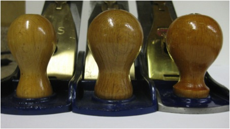
K1 K2 K3
REAR HANDLES
I have noted only 3 styles of rear handle, starting with a ‘chunky’ (H1) , progressing to a more shapely but slightly smaller (H2) and then to a similarly shaped but flat sided (H3) handle. ( I have noted that the base length of H1 is longer than H2 and H3). The depth from the sole to the top of the foot is variable according to the machine operator’s sanding/cutting preferences. Once again, since this was such a relatively small operation, there seems to have been more individual variation in components, and this could be either due to technician hand finishing or the buying in of components from different outside local sources.
Photo below from left to right:
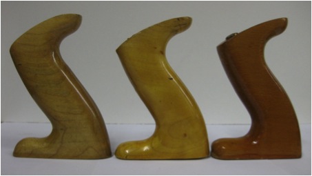 H1 H2 H3
LATERAL LEVER
The first Lateral lever (L1) had the operating ‘finger ‘end as being a single left-hand turned down tab, whereas the second type (L2) had a double (both sides) turned down tab.
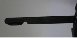
L1
L2
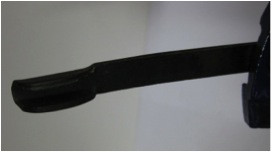
The working (lower) end of L1 is a squared and turned up (like the first Lateral lever produced on STANLEY bench planes in 1885), [which is most curious considering the more efficient Lateral levers produced by so many other makers prior to the start of WS production. The ‘revolving circular disc’ being the most superior, and available on English RECORD planes as early as 1933-1939.] It must therefore have been a financial decision to step back 60 years for this design. L2 shows a marginally more efficient lower (working) bearing surface, in that it is now a raised, but almost a ‘courtesy to a circular’, extension of the Lateral lever [as shown below right.] All levers show the blackened ‘rust-inhibiting’ finish.
Recently I have come to the conclusion that the Lateral lever on WS planes did indeed have a slight bend in the lever. I myself have been guilty of straightening these levers in the past, based upon other maker’s specifications, but having found so many levers, all slightly bent (5 degrees?) at 1.1/2″ from the top end, I must conclude that this was a factory manufactured design to clear the thumb end so as to not scrape on the underside of the blade. It can be seen faintly below on both levers…
L1 L2
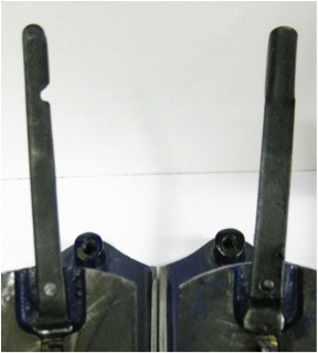
FROG
There were only TWO shapes of frog, the square shouldered style (F1) and the ‘Ogee’ shouldered style (F2). F1 however can be further divided into the first available ‘rounded’ (F1R) formation showing a rounded in-casting below the attachment point of the Lateral lever, and then with the more squared in-casting indentation (F1S). You must note that both types of the F1 style frog [F1R and F1S] came with both types of Lateral Lever (see F1R and F1S below). F1R frog usually has an L1 lever, but I have recently noted that on the larger planes (5.1/2; 6 and 7) F1R seems to have an L2 lever, as shown below:
The F1S frog provisionally had the L1 lever, but quickly transitioned into the L2 lever. You may therefore find F1S with either an L1 (rare…see immediately below) or an L2 lever
 The ‘rare’ F1S with an L1 Lever.
 Left to Right….F1R; F1S then Ogee F2
I have yet to see a Number 4 size plane with an F2 frog, which is very curious, because this frog was also produced during the later production times of number 4 planes, but the F2 frog is only found on the larger and later introduced sized bench planes.
The circular rivet that attaches the lever to the frog at the back either rotated with the lateral lever or was stationary having the lateral lever rotate around the rivet on the top surface. The first earlier method would be the better, more secure method. Most of these circular rivets are ‘blackened’ steel and not over-painted. (as is unfortunately shown below)
FROG SCREWS
These are the screws that hold the frog to the base, and may be either ‘Round’ headed or ‘Cheese’ headed. Generally they were rust inhibited by a Black coating, except for the later screws which were clean steel.
My examples show really no real transition from Round to Cheese headed screws. Basically I think that WS may merely have used the screws that were on hand, and this was driven either financially or by availability , neither is certain. There seems to be a time, early on, when the cheese headed screws were deeply chamfered on the top edge…as shown below right.… but again, this may have just been a manufacturer supply issue.
 ‘Cheese’ head on the left.
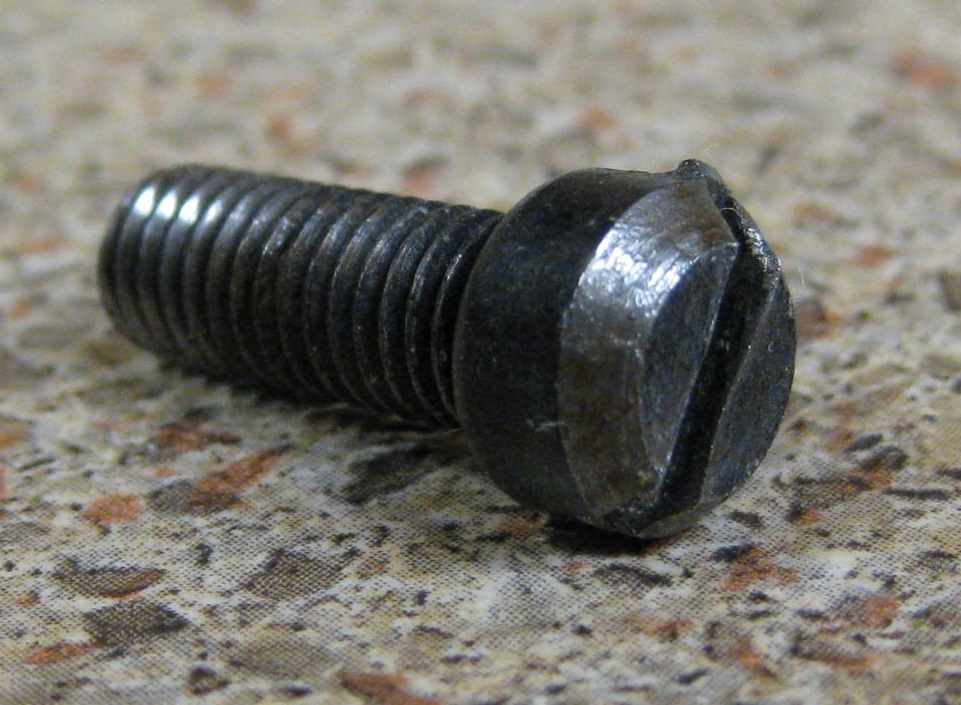
[An interesting point here is that I have THREE WS A4.1/2 planes that contain much larger than normal ‘Round’ headed screws. I had thought that this was an owner modified variation (the screw thread is also much wider) but it may have been a WS modification to absorb the larger load absorbed by the frog on this larger sized plane. Please see the WS A4.1/2 Study.
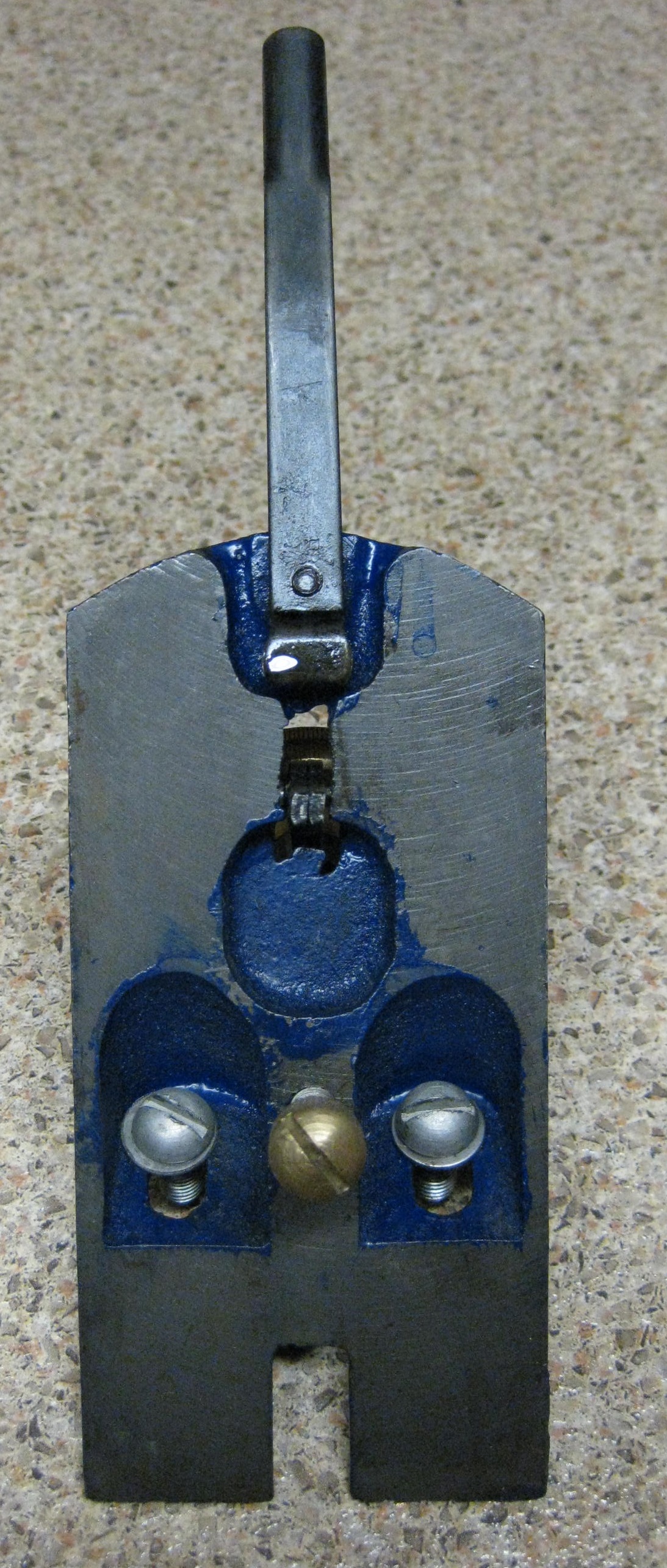
FROG ADJUSTER SCREW AND PLATE
This is the screw that engages with the forked adjuster plate that then moves the frog in relation to the plane’s mouth, with the frog held in place by the Frog screws. The adjuster plate was always finished the same [ ‘black’ rust inhibited] and always had a distinct bend halfway just above the ‘fork’. This bend was’ engineered in’ due to the angle of the frog, and therefore the angle of the Frog Adjuster screw, as it had to be inserted into the base casting. This feature is UNIQUE to WS planes, and this plate should not be hammered flat. Any totally flat plate is either a hammered flat original or a total replacement. The pictures below are representations of the screw and are NOT in any chronological order, and are most definitely not to scale. (But note that the chronological order is currently fairly accurate.)
The smaller diameter section is always 10mm and the larger diameter is 11mm. and the total length of the screw is 23mm [ not to scale.]
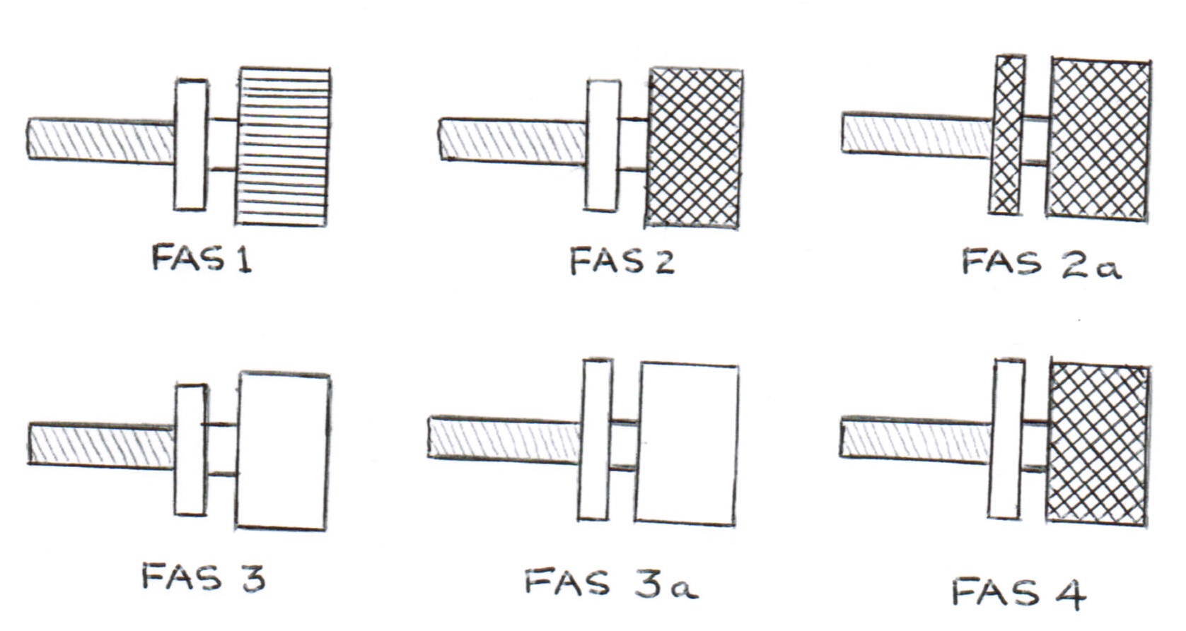
Note: On Type FAS1, I have noted that some have a rounded aspect to the inside of the smaller diameter section (as shown in diagram below):
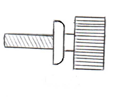
which I shall denote as FAS1R. This was definitely not due to wear on those aspects as it can clearly be seen as a machined on surface.
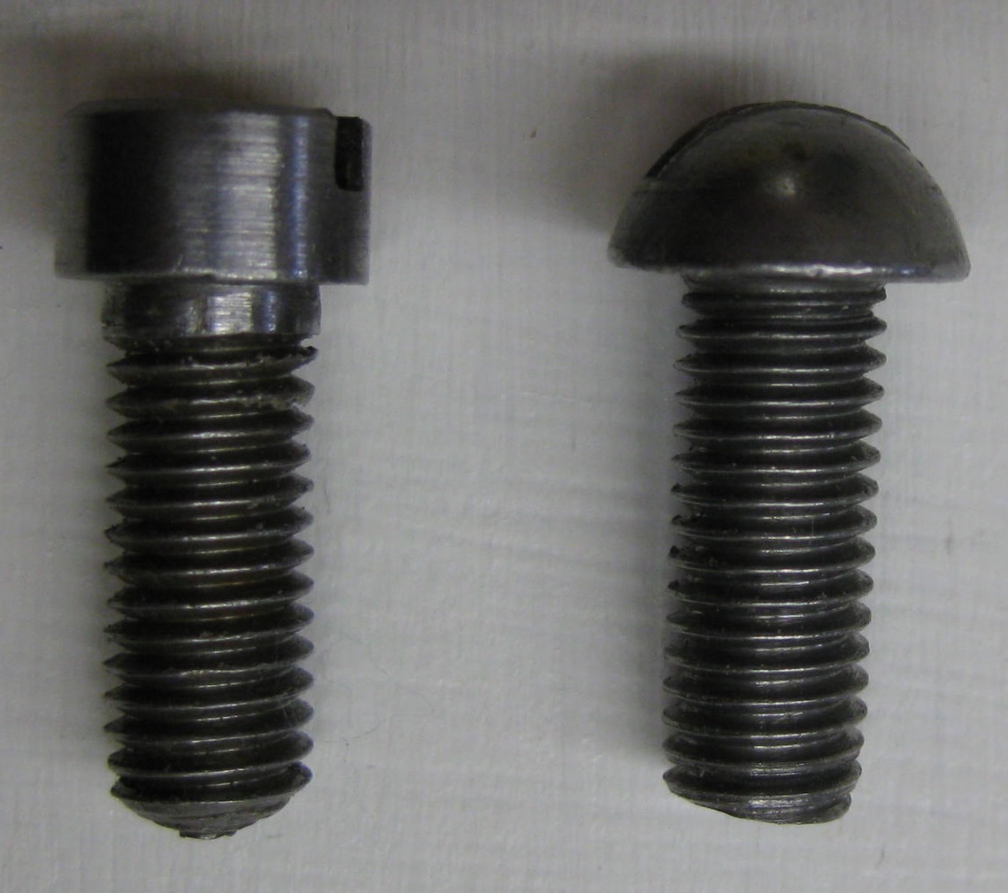
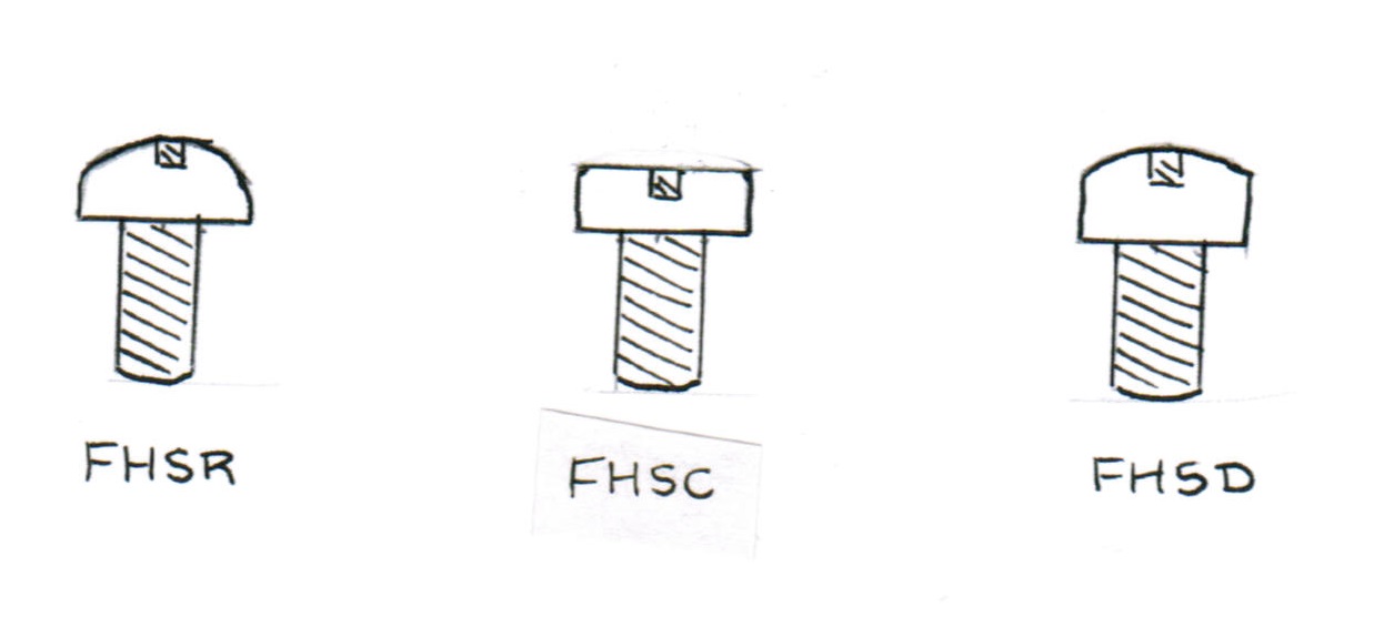
FORK HOLDING SCREWS
These were always blackened screws that hold the forked adjuster plate to the frog. The shape of the screw head changed with time and the first screw had a round head (FHSR), this then changed to a cheese head form (FHSC) and finally to a domed appearance (FHSD). Some of the earlier FHSR screws have a washer (sometimes plated) under the head and many FHSR screws may have an included washer and are the same length as the frog holding screws. Very early examples may show a longer plated bolt [much longer than the frog holding screw] and a plated washer.
 CAP IRON
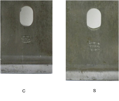
There were only 2 ‘styles’ of cap iron and the differences are quite small. They all seem to have been ‘stamped out’ from mild steel with maybe some finish grinding to the edges.
The first cap iron, labelled ‘C’ [ because the WS motif seems to be almost ‘Cast’ into the steel.] has the WS letters somewhat blurred in outline and present a wider look to the lines of the letters than the second style (‘S’) [ because the WS motif seems to be Stamped into the steel] and which has the WS letters quite sharp in outline.
‘C’ also looks slightly smaller overall than ‘S’.
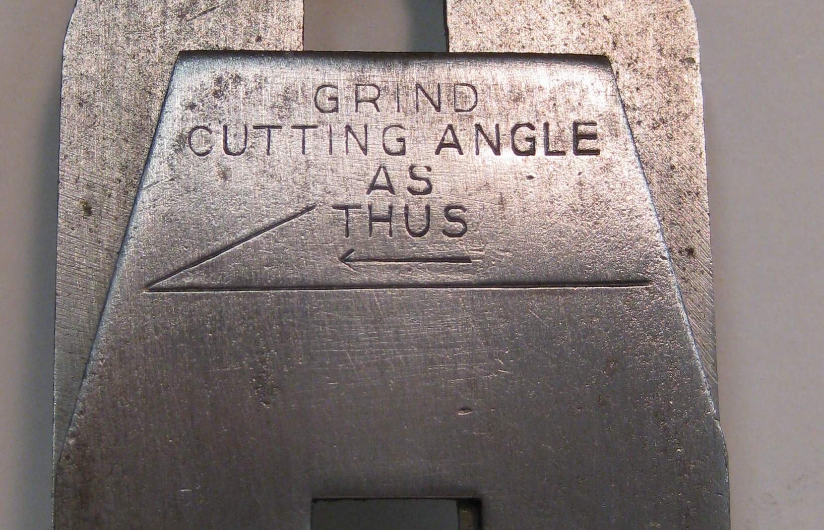
All of these cap irons were marked towards the top: ‘GRIND CUTTING ANGLE AS THUS‘ to give the user a template for the correct grinding angle of the iron.
 ALL of the undersides of the WS Cap irons look like they have a ‘wire-brushed’ type finish, whereas most other makers had cap-irons that showed a blackened (straight-from-the-forge) appearance underneath.
BLADE
The blade [cutter] was always of the same shape….with angled shoulders having a sharp corner to the top edge. There was never any distinct rounding of the shoulders or of the top corners. (In other words they had a ‘classical’ look as opposed to the softer lines of more modern irons.)

The blades were probably always made in SHEFFIELD (firm unknown) as I am sure that WS did not have the facility to produce their own cutters and these were always ‘stamped out’ showing the rough edges, [i.e. not having had any finish grinding/sanding].
The very first blades did not have the WS motif, but were merely stamped ‘Warranted Sheffield Cast Steel’ (B1).
(B2) had ‘Sheffield WS Cast Steel’ , all the letters being in an arc, with a larger ‘WS’ and the total depth of the stamp being 16mm.
(B3) had ‘Sheffield WS Cast Steel’ , ‘Sheffield’ being in an arc, but ‘Cast steel’ is in a straight line and 11mm is the total depth of the stamp. (but with a smaller WS than B2)
(B3a) is the same as B3, but the letters are smaller, although ‘WS’ is the same size, with only 9mm as the total depth of the stamp.
(B2a) is a stamping that only applies to the Spokeshaves, never having been seen on planes. I am sure that the numbering is in correct order as the stamp is similar to B2 but the total depth is down to 13mm. You will note that the stamp depths seem to get smaller as time went on.
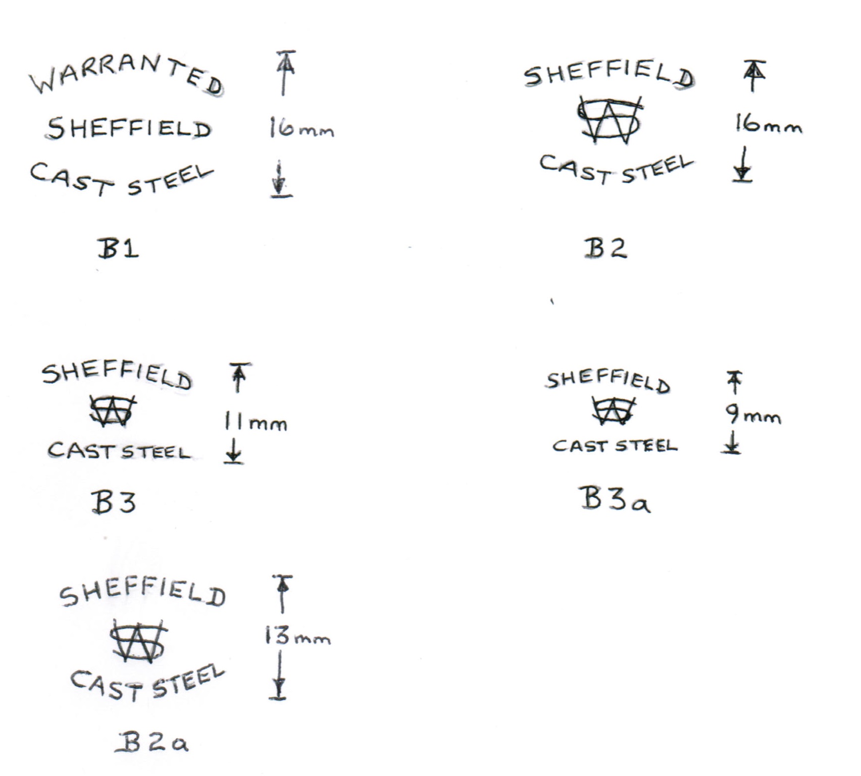
I have only seen two examples of B3a, (one on a spokeshave) and therefore this mark may be quite rare.
Please note that the numeration is, in my estimation, fairly accurate and chronological.
There is growing evidence that some of the later blades were not stamped with any markings at all.
CAP SCREWS
These screws secured the cap-iron to the blade and were usually ‘blackened’. They are 1.6cm diameter, 4mm thick and have a wide slot of 3mm (to accommodate the Brass Lever Cap ‘screwdriver’).
I have identified 3 types: the first issued has only vertical parallel knurling CS1, the second issued has a coarse cross knurling CS2 , and the third issued CS3 has cross knurling that seems quite feint….almost like a ‘filed off’ CS2.
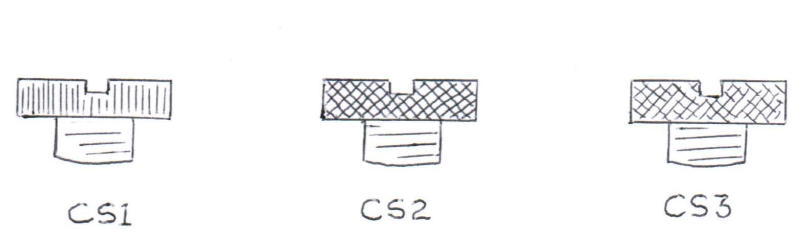
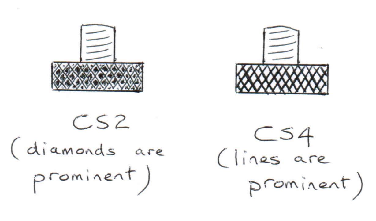
But there are now differences noted in CS2….
In CS2 the diamond areas are prominent (i.e. are the top surface and the lines between are set below that surface) and presently this seems to be the earlier model. In CS4 the lines between the diamonds are at the surface and the diamond area is set below those lines. I will try to upgrade the line drawings and the Studies as time and information permits.
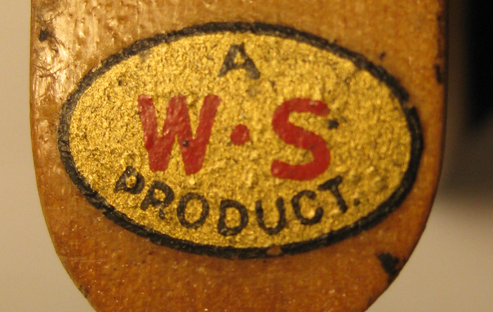
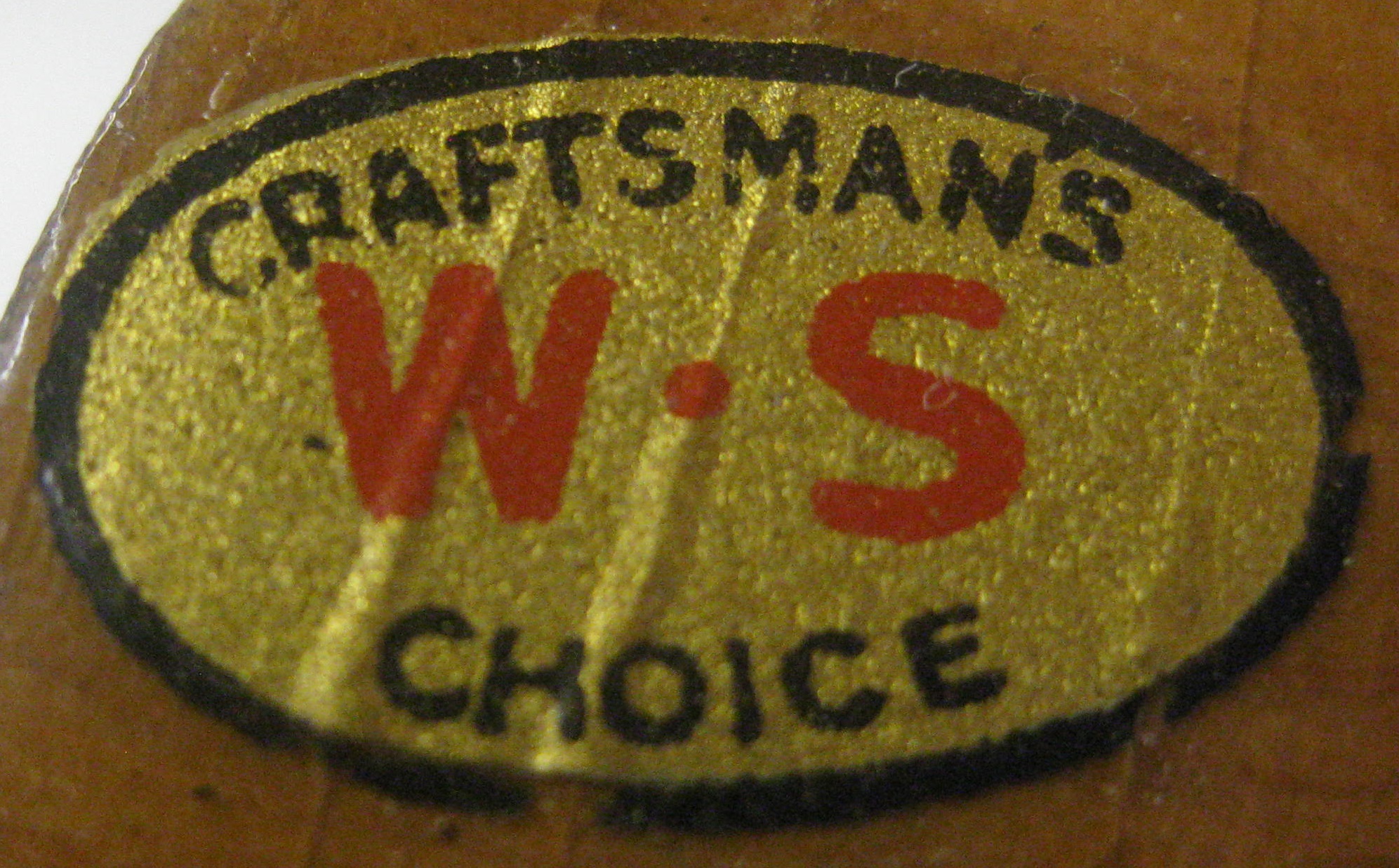
REAR HANDLE TRANSFER
This water transfer was placed on the top of the rear handle throughout production. [ except at the very beginning and the very end of WS manufacturing, when there appears to have been no transfer applied.]
To date there are only 2 known transfers:
RHT1 (i.e. after the no transfer period) indicates: ‘A WS PRODUCT’
RHT2 indicates: ‘CRAFTMAN’S WS CHOICE ’
There seems to be no consistent orientation in which these transfers were applied to the handle, either readable from the front of the plane or from the back of the plane.
RHT1
RHT2
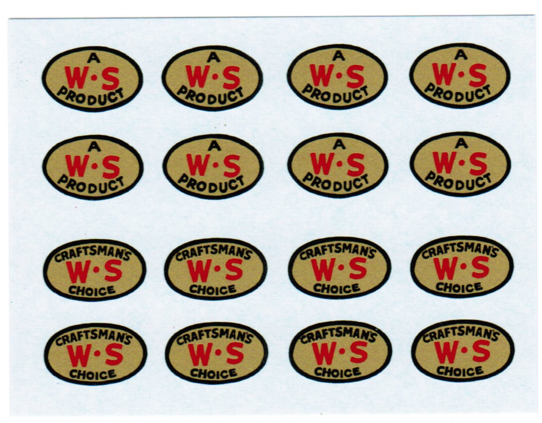
PLEASE NOTE : I have really great REPRODUCTION Water Transfer Slides of RHT1 and RHT2
If you are interested in buying a few or a lot, please contact me through this site. It would appear that the earlier RHT1 is certainly a lesser used variety, and therefore I will sell this variety at $1CAN for each one + postage, even though I will be losing money at that price. Below is a photo of a sheet of transfers showing 8 of each kind, so it would be easier, all around, if I could sell multiples of 4 ($6CAN for RHT2 and $4CAN for RHT1)
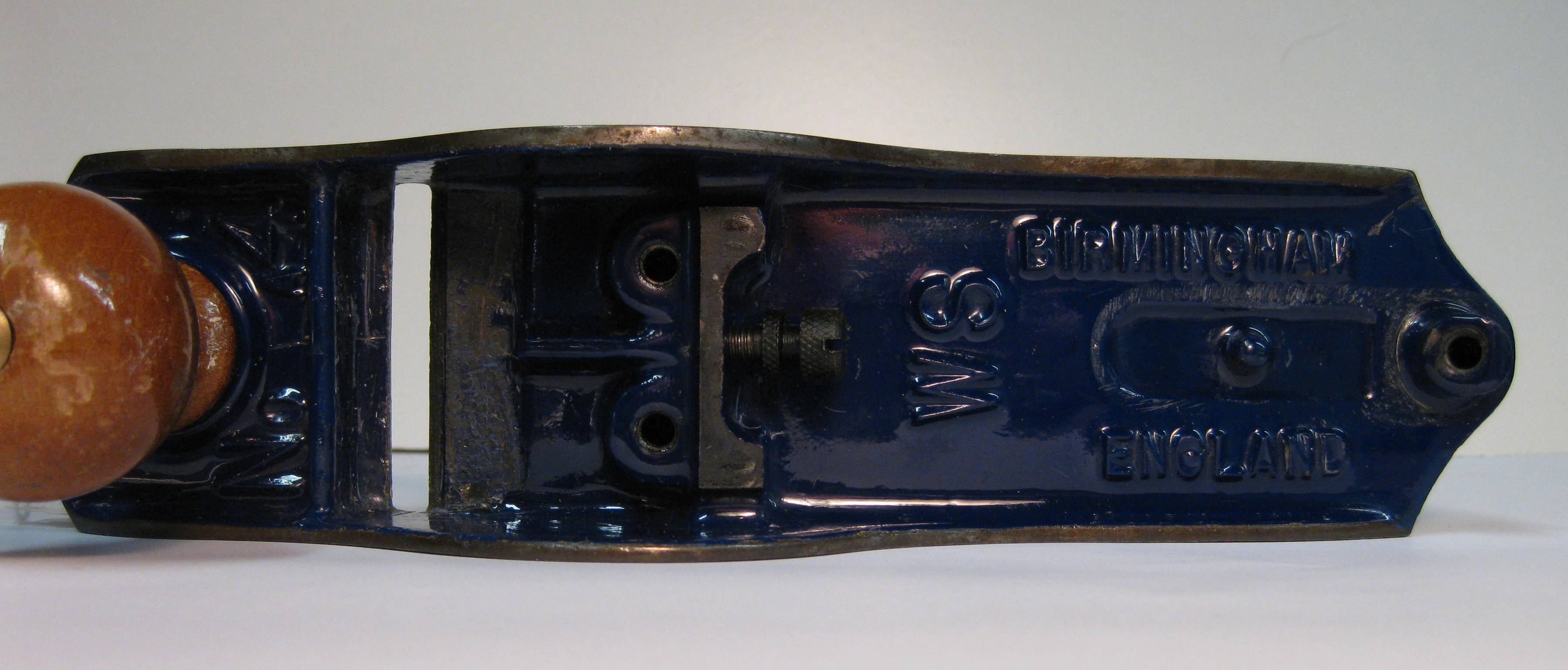
BASE AND MARKINGS
These are the casting marks that are on the base and are linked to the side profile.
BM1
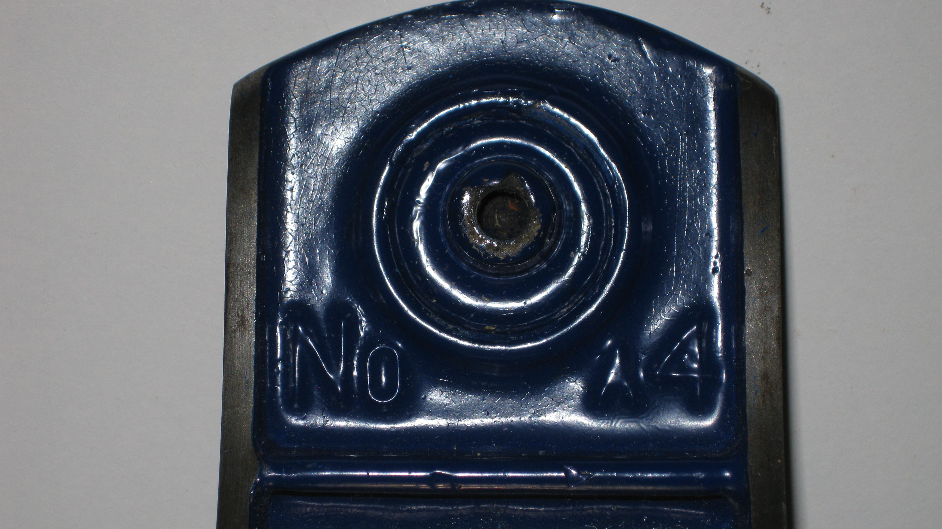
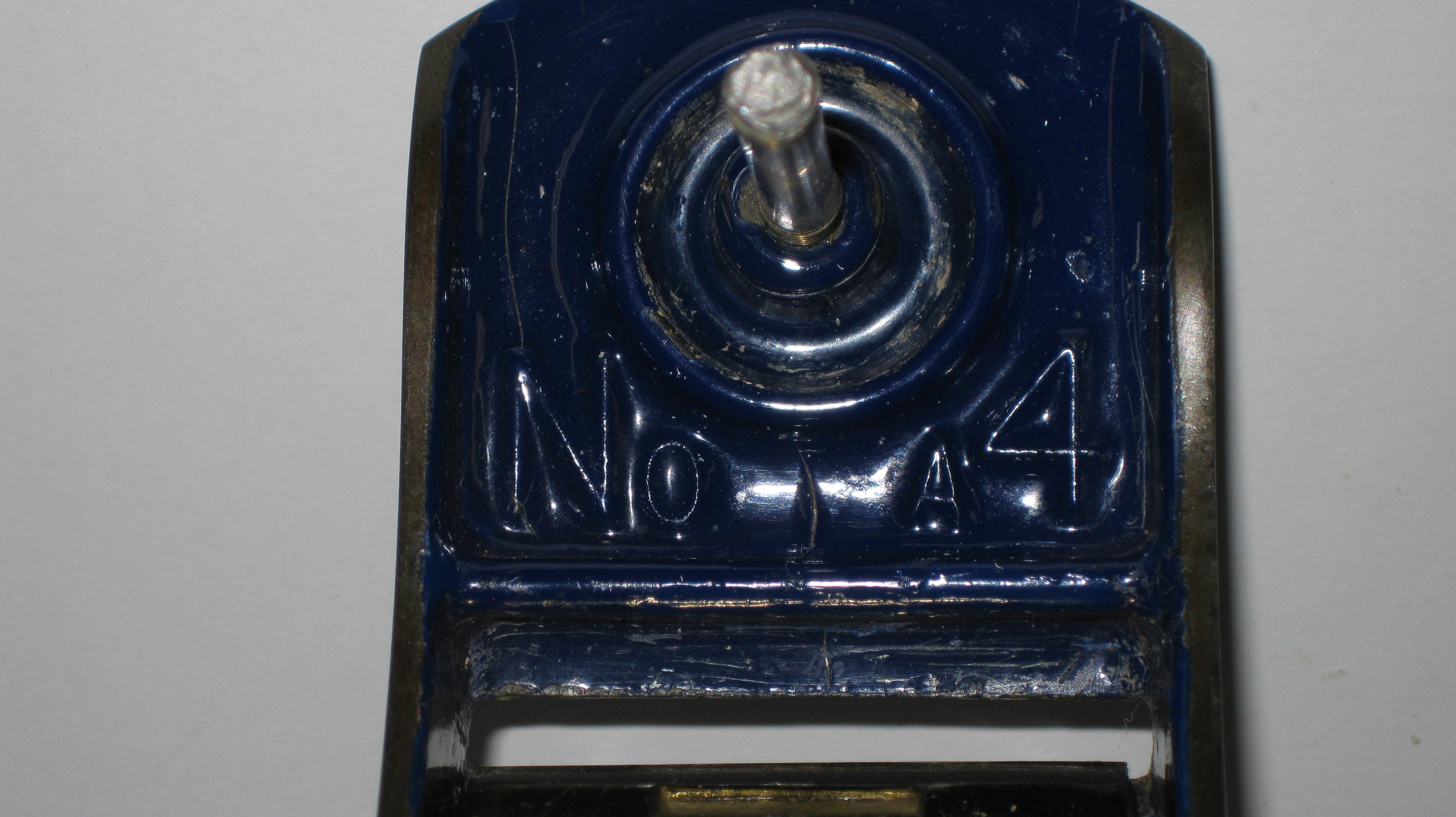
This was the original casting issued by WS at the very start of plane production and these No.4 planes had the mark of No 4 cast in front of the front knob.
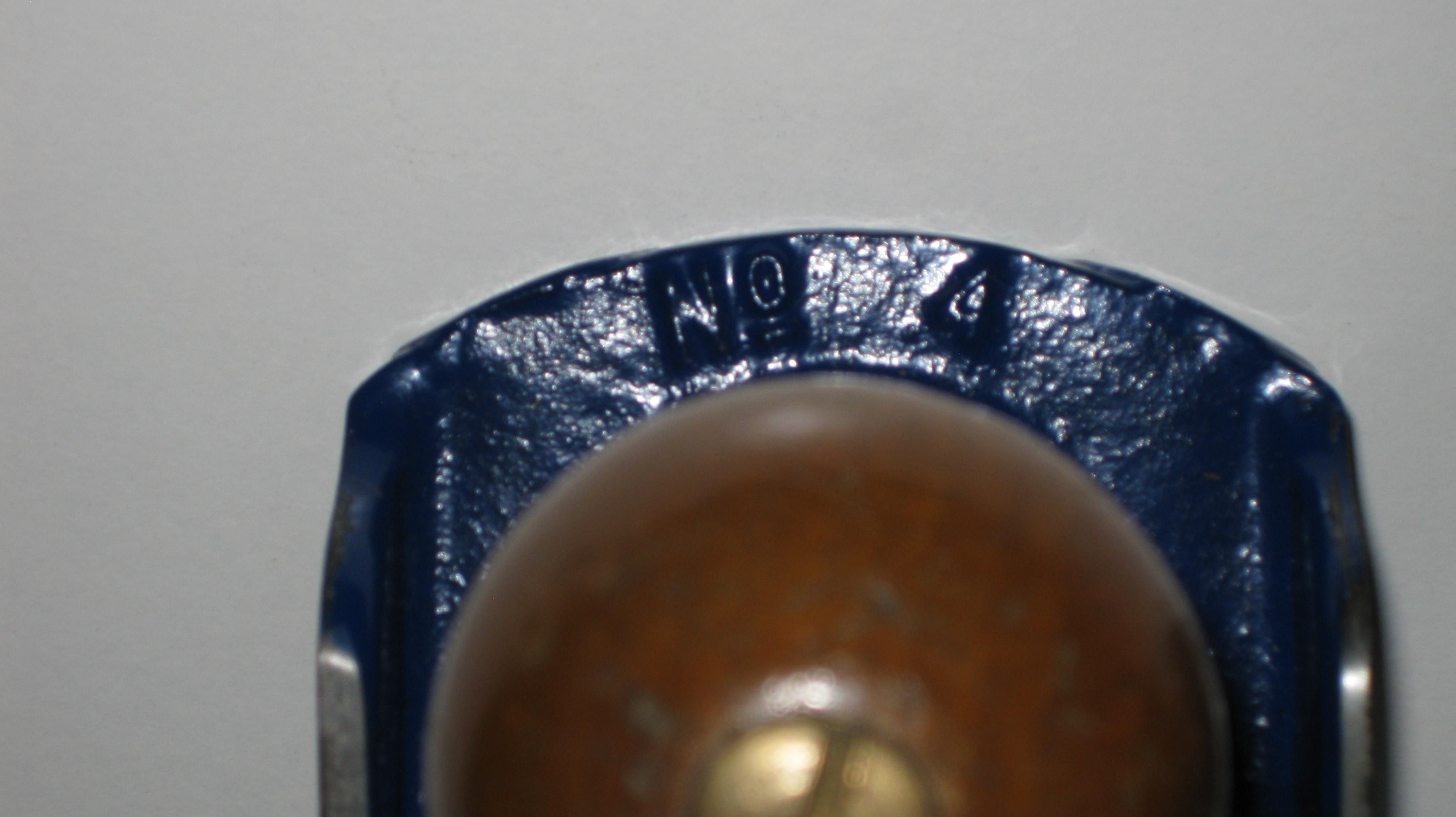
BM1
And the behind the frog markings were like this:
BM1
WS was cast on the right hand side in front of the rear handle and the words BIRMINGHAM and ENGLAND were in small type on either side of the rear handle.
PLEASE NOTE that the ‘step up’ evident to the deep side face from the front edge (shown below), and the parallel to base proportions are shared by both BM1 and BM2.
BM2
The second casting mark was very similar, but the number had changed to No A4 although the markings to the rear of the frog were exactly the same as BM1 Models BM1 and BM2 had the front edge painted, but all models subsequently had a clean metal front edge.
BM2
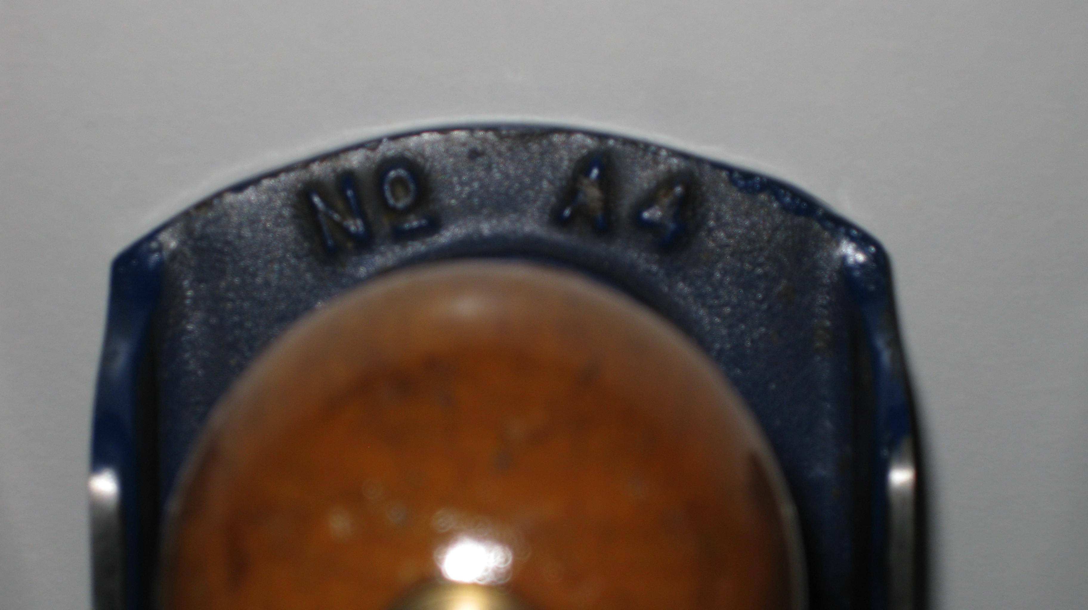
BM3
The third casting mark had the number moved to behind the front knob, and is cast as No A4. Please note the small N and the small 4. 10mm (in comparison to BM4) :
BM3
The BIRMINGHAM and ENGLAND were cast in the same size as BM1 and BM2, but ‘BIRMINGHAM‘ is shifted slightly more forward. The WS now appears in LARGE letters across the plane in front of the rear handle:
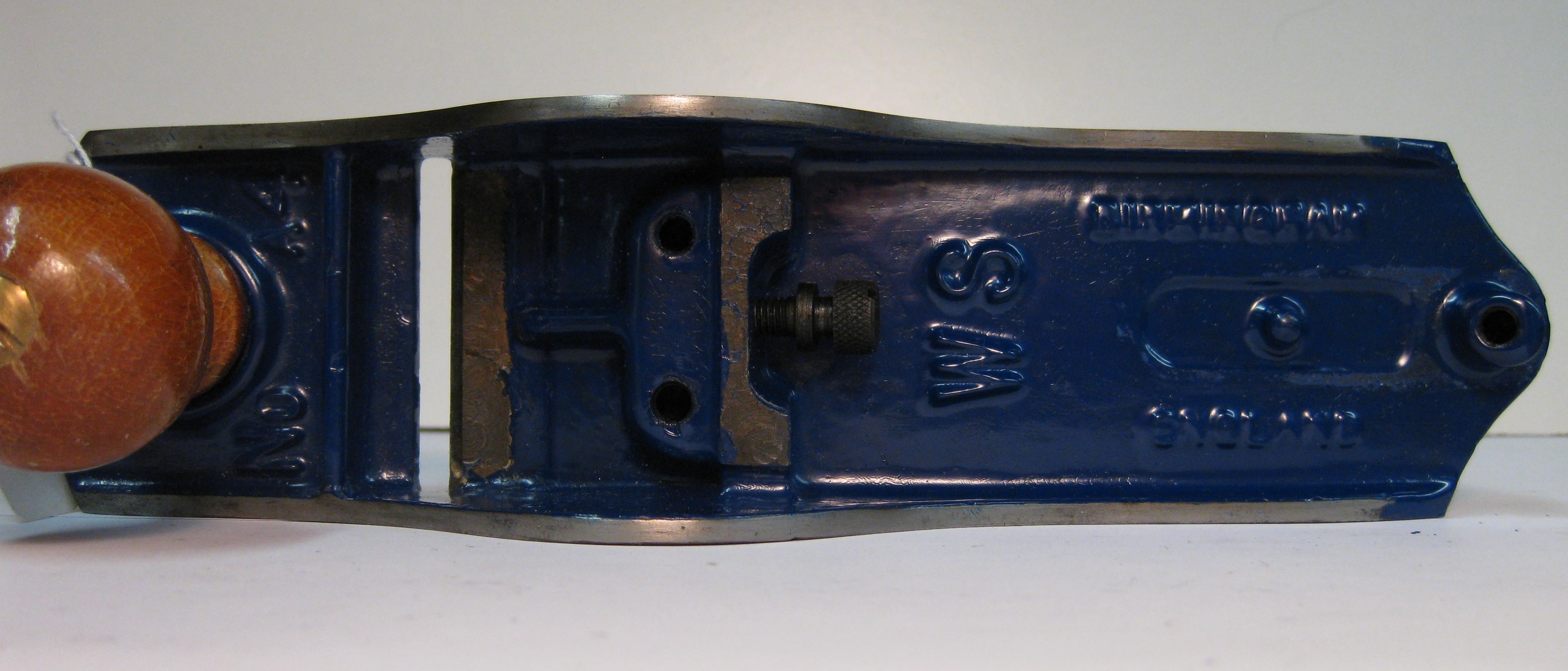 BM3
BM3
The side profile changes drastically from BM1 /BM2 to BM3 in that there is now no ‘step up’ at the side front, it merely has a slow transition into a slope that culminates at the top of the cheek, and then there is a slow curve down to the rear handle with little ‘parallel to bottom’ usage apparent.
BM3
BM4
BM4 side profile is very similar to BM3 but seems to have more depth at the front end and less depth towards the rear, but the MAJOR CHANGE is that the N and the 4 are much taller behind the front knob, compared to BM3, and BIRMINGHAM and ENGLAND now appear as much larger letters.
 BM4
BM4
BM4 (Note the taller N and taller 4 at 13mm compared with 10mm on BM3)
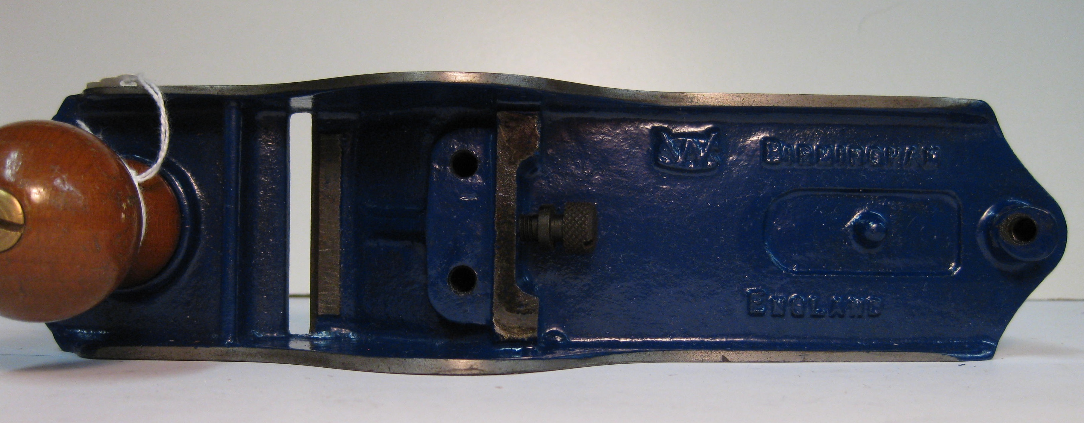
Above is an example of BM4 showing enlarged lettering of BIRMINGHAM and ENGLAND, and new Frog Landing area type 3 FLA3 (see below).
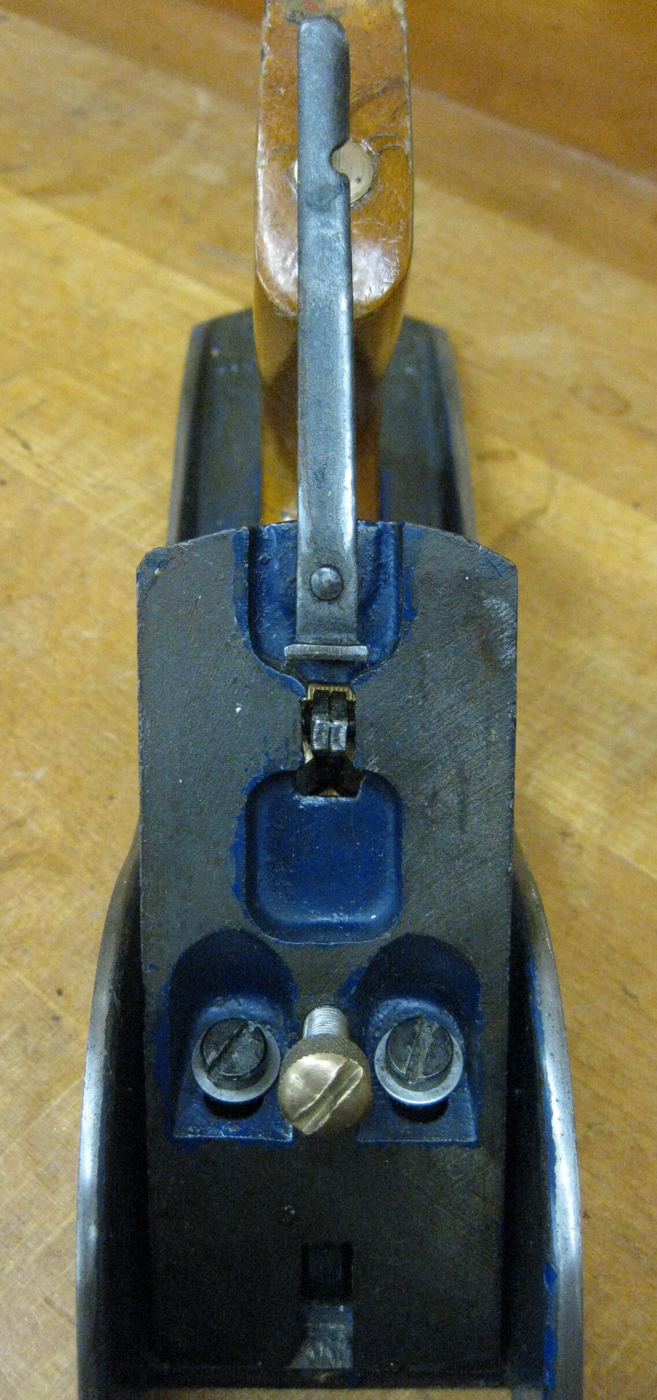
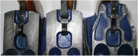
FROG LANDING AREA
From the above Base Markings photos it can easily be seen that the frog landing areas (FLA) [where the frog actually contacts the base at the mouth] did change with time. The earliest FLA1 shows a rectangular raised area just rear of the mouth, but FLA2 has a wide machined out area as does FLA3. FLA3 also has a totally redesigned casting area where the frog screws attach to the base, and is therefore associated with Base Marking BM4 .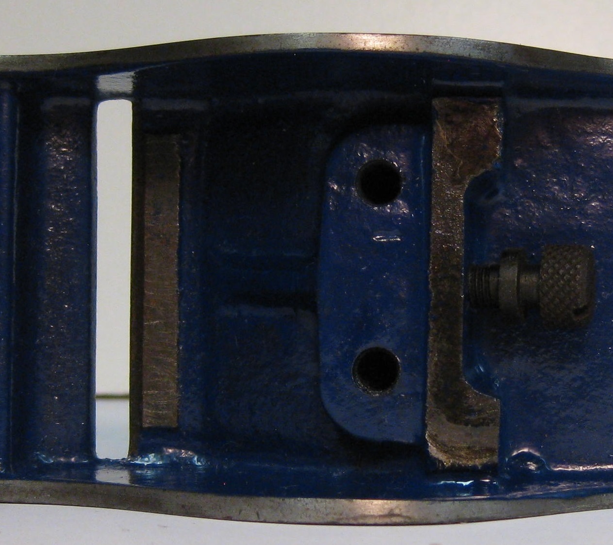
FLA1
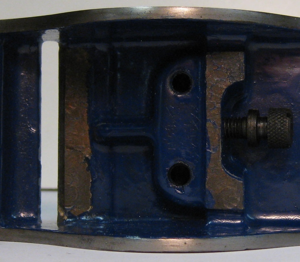
FLA2
FLA3
BRASS ATTACHMENT NUTS AND STEEL RODS
These are the brass nuts that hold the front knob and the rear handle tight, and are screwed onto threaded rods that are themselves then screwed into the base. These same size nuts were always the same throughout WS plane production and common to all sizes of bench planes. They were parallel from base to top, but having a circular brim as shown below.
Any nuts that are found that have a ‘waist’ are certainly not original nuts, and will probably therefore be a RECORD substitute. (based upon thread size etc.)
The rods always had ‘rolled’ threads as opposed to ‘cut’ threads. [How to tell the difference…’cut’ threads (older) have the same diameter as the rod, the thread ‘gaps’ being removed from the rod by a cutter. ‘Rolled’ threads have a diameter greater than the rod itself, because the metal in the ‘gaps’ has been squeezed up by the rolling die to form the threads.]
I have noted that the rod for the knob appears to have a shorter threaded portion at the top to take the brass nut down to the end of the threads. But I have also seen many rear handle rods that show [in the top portion of thread to take the brass nut] that the thread has been struck about 7mm from the end in order to limit the travel down of the brass nut. I do not know why the rear handle rod threads would not emulate those of the front knob in executing the restricted travel for the nut.
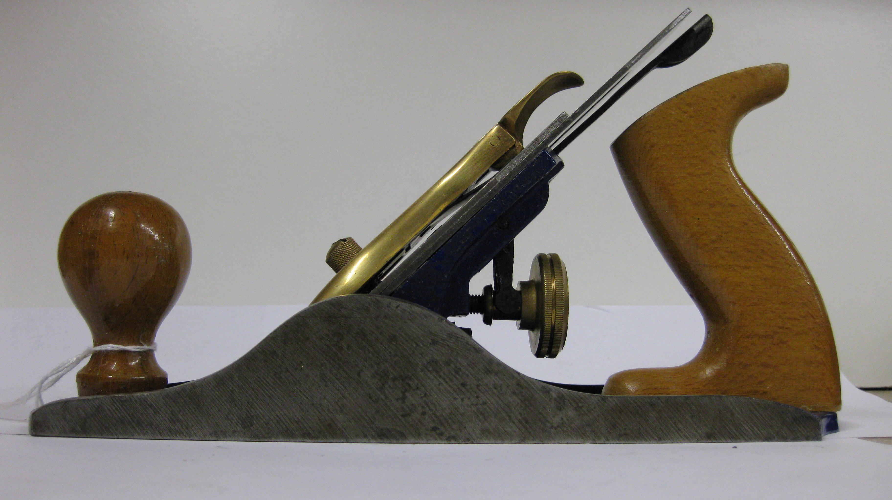
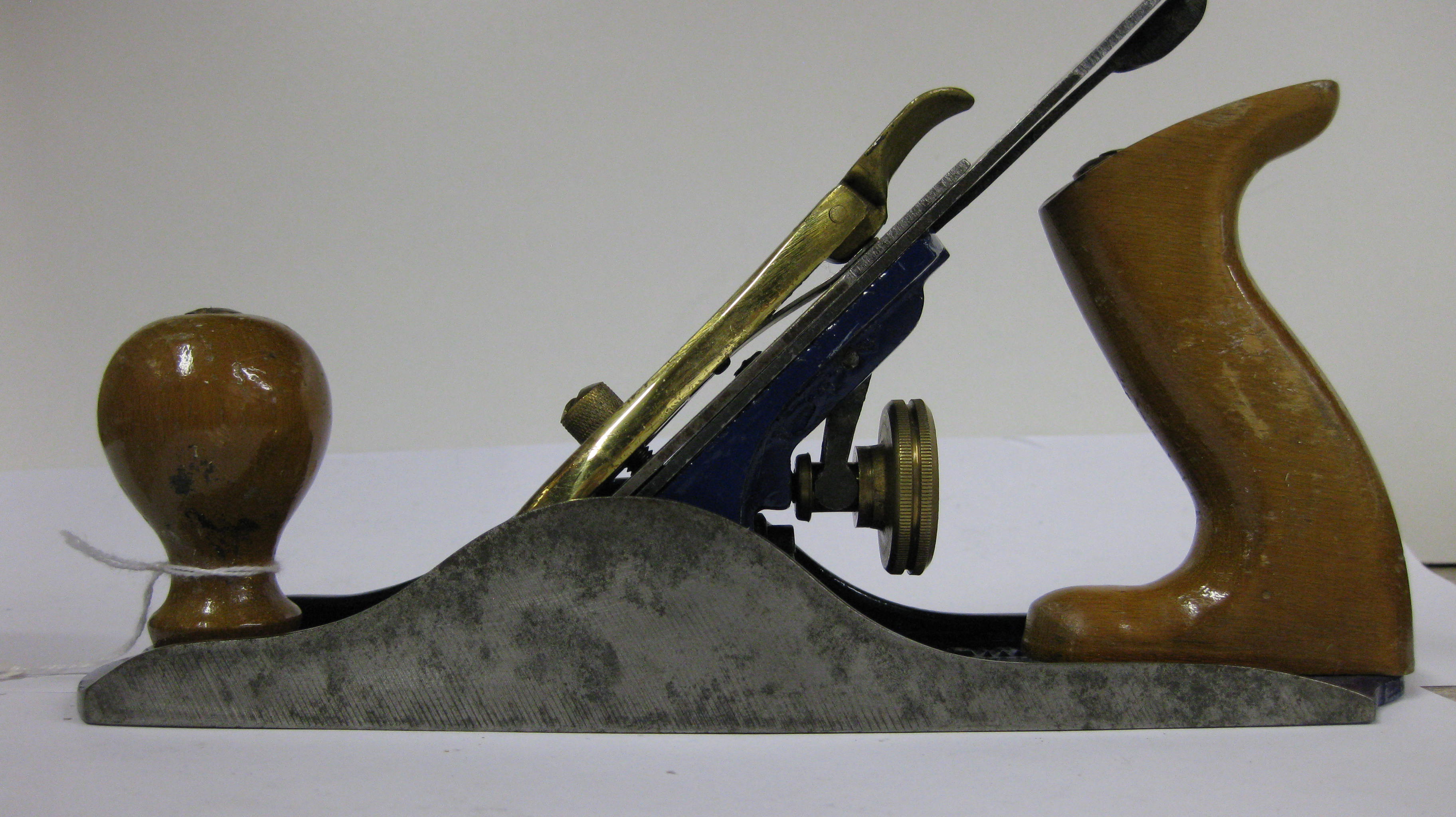
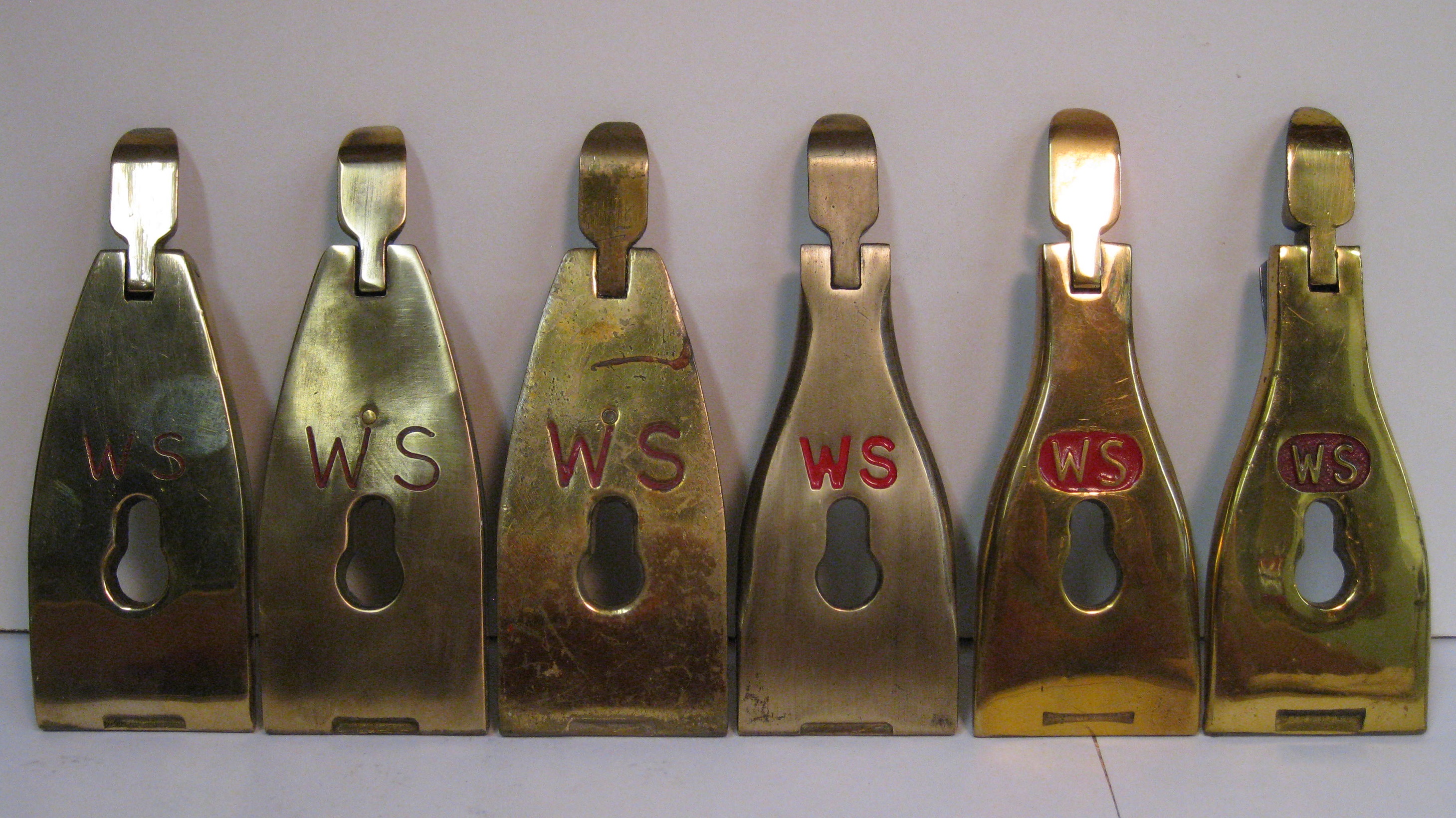
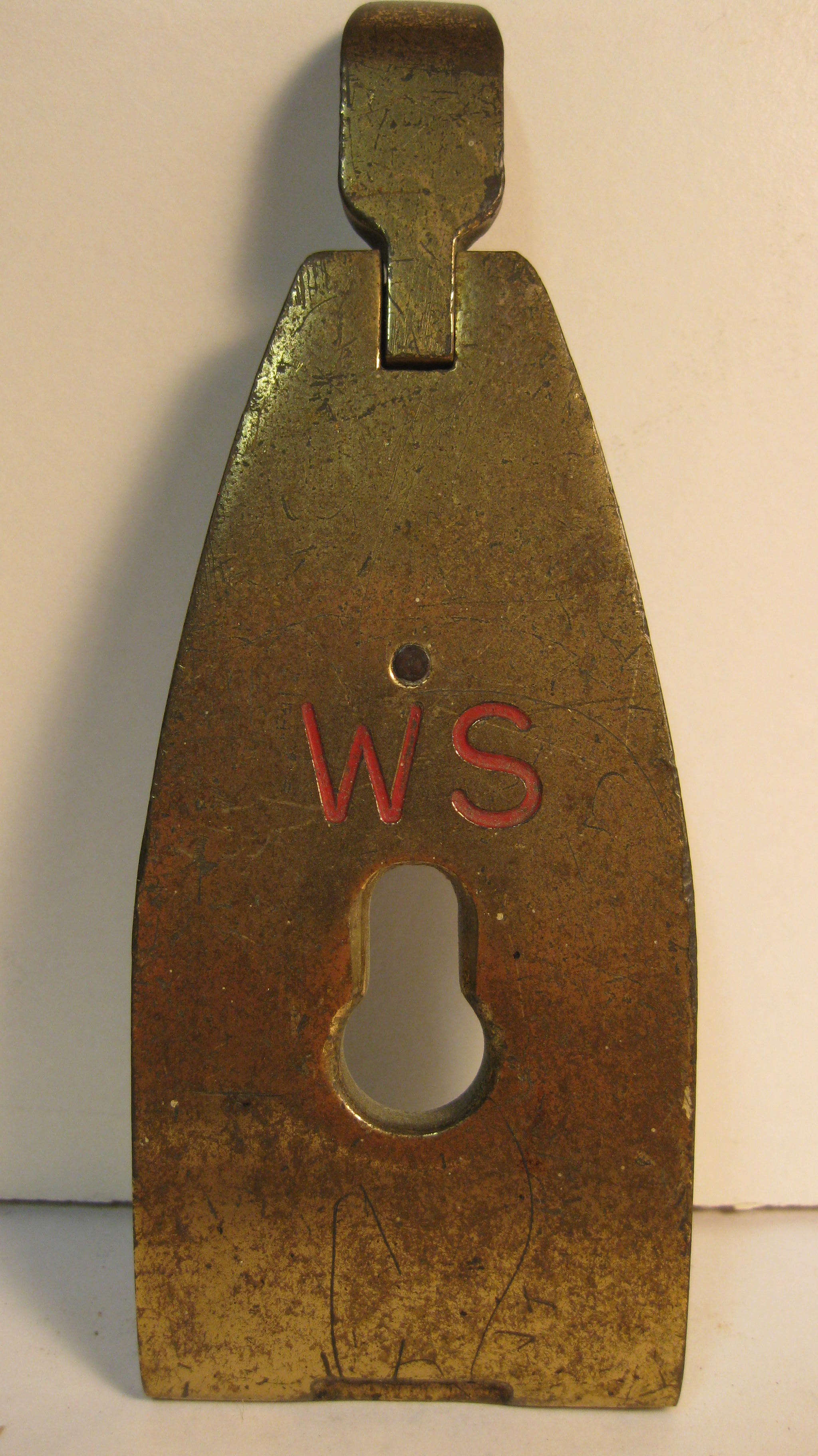
LEVER CAP
The most distinguishing feature of the WS bench plane is that the Lever Cap was made of solid Brass and this had various thicknesses of a Lacquer coating applied. The top ‘shoulders’ were always square and flat in the Number 4 and 5 planes, but were rounded over [back to front] in all other size planes.
From a manufacturer’s insert [in a boxed A4 plane that I have] it is stated that the Brass lever cap (or as WS called it..Clamping Plate) is ‘made from a high tensile non-ferrous alloy, giving approximately three times the strength of ordinary iron castings, thus ensuring it non-breakable if dropped’
The same insert also informs us that at the ‘leading edge’ of the ‘ Clamping Plate’, provision has been made to use that area in ‘Screw-driver’ fashion when the iron has to be dismantled’, and this is the only company that designed in this useful feature. Note that the slot in the ‘Cap Screw’ of WS planes is machined 3mm wide to accommodate the Lever Cap ‘screwdriver’. Any Cap Screws found with a narrower slot are therefore not original. Other manufacturers did not recommend that their lever caps be used to unscrew the cap iron from the blade, because of the possible breakage of their cast iron Lever caps under such pressure.
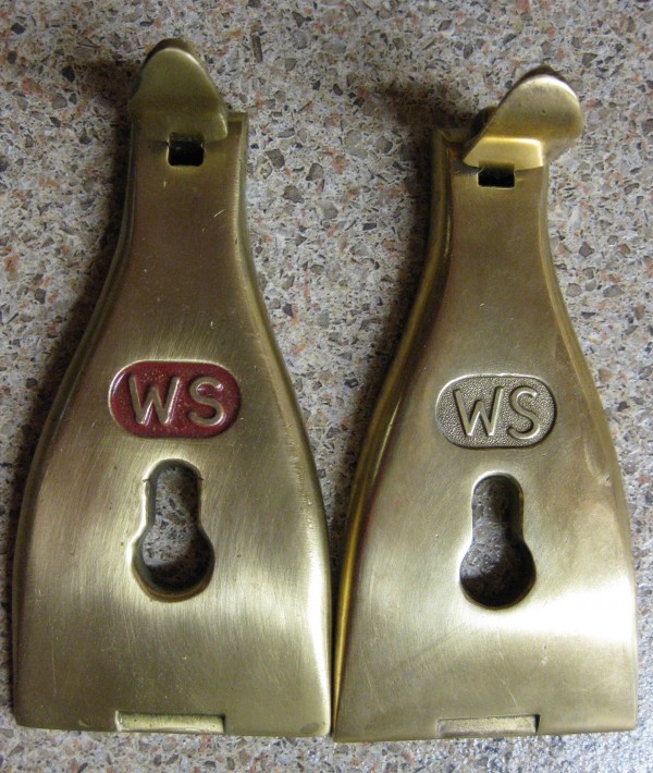
Below is a photo of the different Lever Caps that I have so far identified, and I have attempted to list them in the order that I think that they may have occurred. Note the ‘screwdriver’ on all of the leading edges.
From Left to Right..LC1; LC2; LC2a; LC3; LC4 and LC5
LC1
The very first Lever Cap?
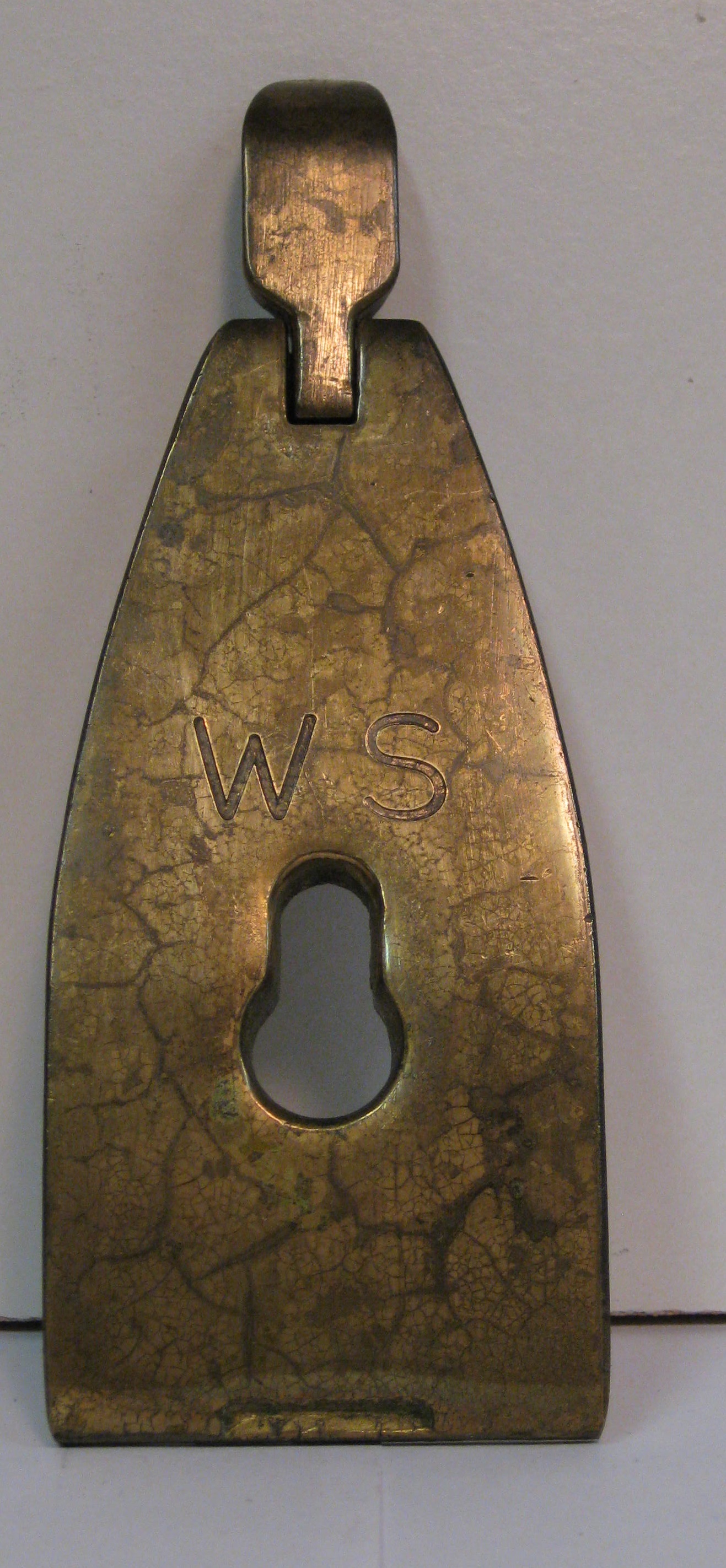
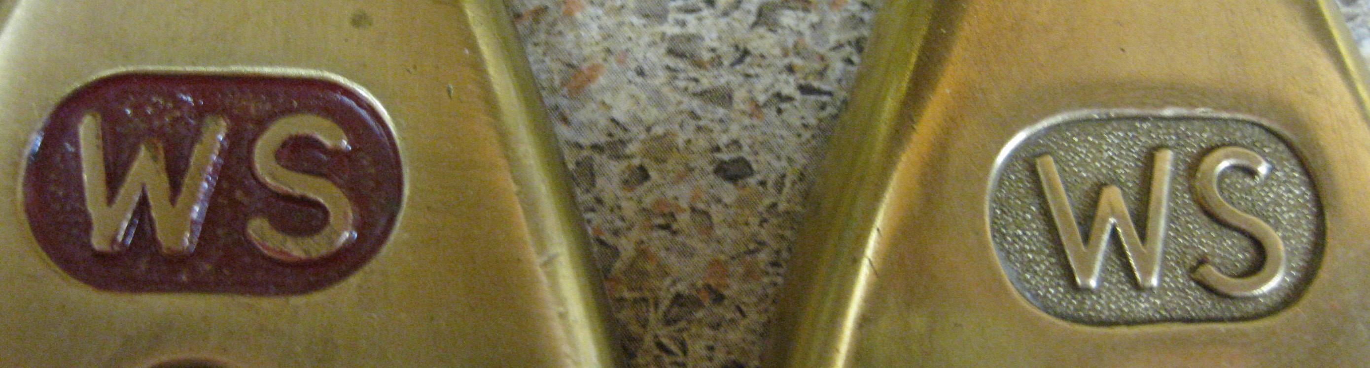
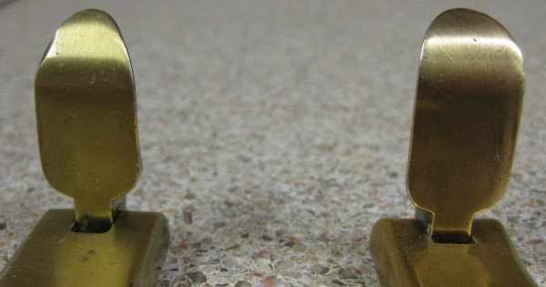
The very first Lever Caps LC1 did not have any red infill paint in the WS letters, as shown immediately above, but I will treat them all as LC1. The WS letters look almost as if they have been inscribed with a hand engraver (probably through a template) and there is a 5mm. gap between the letters which are themselves 10mm high. The rear spring is secured by a round headed steel rivet which may have been brass coloured. Later examples of LC1 may have a RED infill to the WS letters. The weight of these Lever Caps provides a Superior dampening effect for the blade assembly.
[The RAPIER 400 (made by BT Anglo Scottish Tool Co. Ltd. of Gateshead) and other manufacturers) also had later similar shaped lever caps.].
LC1a
Exactly as LC1, but the round headed brass coloured rivet has been ground to a flat, and the top surface may show Red infill to the WS letters.
LC2
Has RED paint infill in the WS letters and these letters have increased in size to 14mm high and 6mm between the letters, but still appear to be hand engraved. The rivet securing the rear spring is brass and shows through to the front of the cap at the end of the W letter. This rivet, behind the spring, is 5mm in diameter and is flat.
LC2a
Is the same as LC2 but the letters are thicker and look cast into the cap and are Red infill painted. The brass rivet again shows through to the front but on the reverse side is flat and 10mm in diameter. The varnish on the top face seems to have a green tinge.
LC2b
The same as LC2a ,but the letters are now only 11mm high (cf 14mm). The brass rivet is exactly the same front and back as LC2a, and it is hard to know which came first, LC2a or LC2b.
LC3
Shows a change in lever outline to the same common profile as other makes. (an OGEE like profile)
The WS letters are now cast into the face of the Cap and are Red infill painted. WS is 11mm high and there is 2mm between the letters. The steel rivet does not show through to the front, but has a ‘flat’ ground on it at the back.
LC4
The WS letters are showed as a raised casting inside an oval window. The Red background painted oval window is finely stippled and is 23mm wide. The letters are 10mm high and with 2mm between them, and the spring is secured by a small round headed steel but brass coloured rivet which has been slightly peened over.
I have found a slight variation to this pattern designated LC4a which has a 6mm brass plated, round head steel rivet ground with a flat on it , but this may be too small a variation to merit a full difference as I have seen only one.
LC4b
Above are 3 photos of LC4b showing a much more ‘relaxed’ S than previously, and a chunkier lever (shown on the right and not as finely drawn to a point as LC4.) The middle meeting point of the two vees forming the ‘W‘ shows a flat top. With this and the relaxed ‘S’, you can identify this cap from the regular finely stippled LC4
LC4b may only be seen on the 2.3/8″ Lever caps ( i.e. A4.1/2; A5.1/2; A6 and A7). I have conflicting evidence (based upon small samplings) and therefore I cannot at this stage indicate when these caps were introduced/made. [AGAIN I have come up against information that leads me to believe that, at any one time, WS plane compilers merely selected the required item from a vast homogenous bin of like products which may have come from different suppliers]. Each of my 5 examples of this Lever Cap show the same spring securing rivet as on the underside of LC4 (a small brass coloured steel rivet peened over showing a radial crack). I have one LC4b [shown above] that does NOT have Red infill painting (like an LC7), but has all the other LC4b characteristics.
LC5
Almost the same as LC4 but the background is coarsely stippled. The letters are smaller at 8mm high with 2mm between them. and the oval window is now only 21mm wide. The red infill paint appears to be more crimson than before and the top face of the brass body has a fairly thick yellow lacquer coating.
The rivet is unusual in that it is small with a steel core inside a brass surround and has been peened over on the back spring, showing radial crack(s) in the brass portion. This is difficult to discern, sometimes you can see the steel outline, sometimes not.
LC6
As per LC5 but the now totally steel rivet has a flat ground on it at the spring attachment.
LC7
As LC6 but it has no red paint in the stippled background.
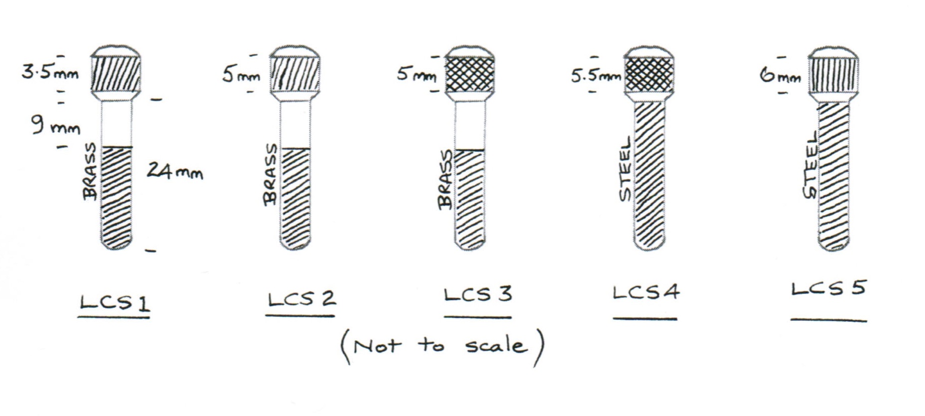
LEVER CAP SCREWS
The Lever Cap screws were initially all brass and then were transitioned into a brass head with a steel thread.
LCS1 has a quite narrow 3.5mm band of slightly slanted straight line knurling. The band depth increased to 5mm in LCS2. Some earlier screws show a pronounced rounding to the top surface. [LCS1 and LCS2 may be the same, but this may be only due to ‘machinist’s tolerances’.]
LCS3 has cross knurling of the brass head but still at 5mm band depth.
LCS4 has a band of cross knurling of around 5.5-6mm and a steel screw thread all the way up to the brass head.
LCS5 has a band of straight line knurling of approximately 6mm depth and a steel screw thread all the way up to the brass head.
I have noted some small differences in lengths and other dimensions, but nothing that would lead me to add additional styles. So the dimensions given here should be considered nominal.
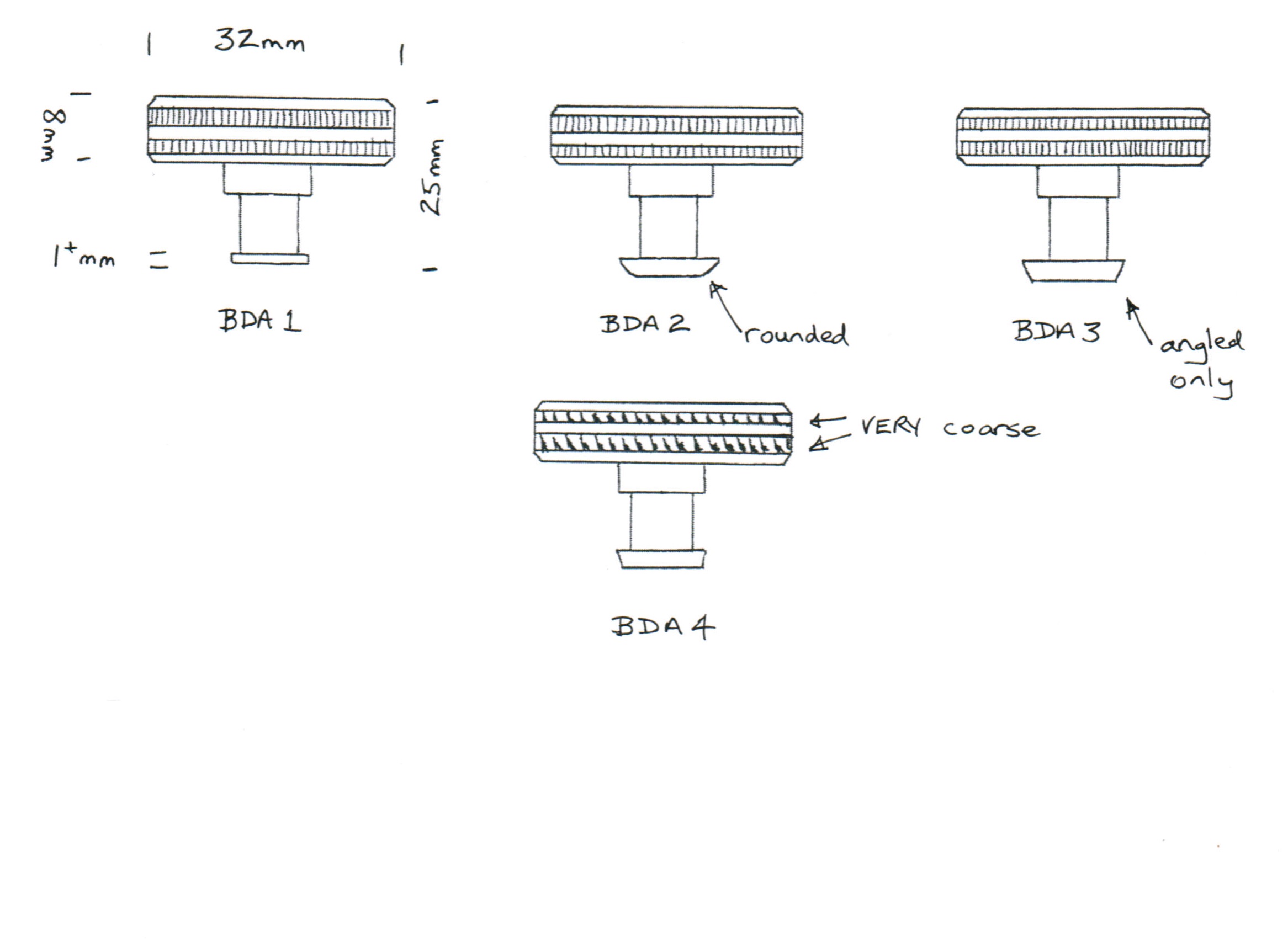
BRASS DEPTH ADJUSTER
The circular brass depth adjuster was very much the same during the whole course of production and the differences are quite hard to diagnose .
All the knurling however was parallel to the screw, except BDA4.
The main differences are that BDA1 has a very thin front end (about 1mm+). Both BDA2 and BDA3 are easy to confuse. The front end of BDA2 is somewhat rounded and thicker (enabling a closer adjustment of the unit towards the frog and therefore more useful travel of the stirrup), whereas the BDA3 has a chamfered edge to more easily accommodate the same adjustment.
BDA4 is easy to spot, as the whole article seems quite rough, as if it is just a straight casting from the mould (as opposed to a machining of the casting). The knurling is coarse and very rough and this is probably the last issue from WS, which is very disappointing, as most other aspects of the product seem to have improved over time.
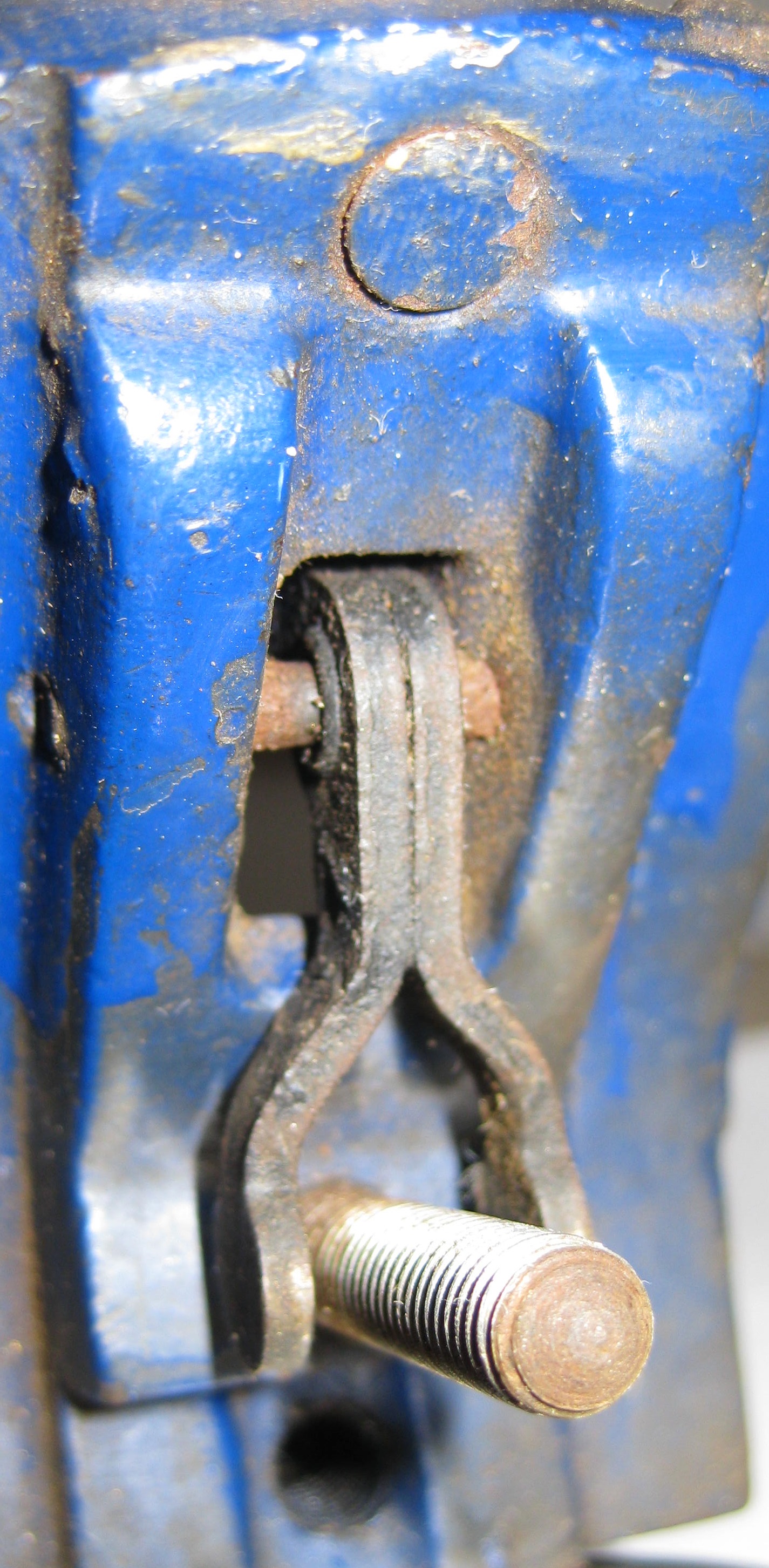
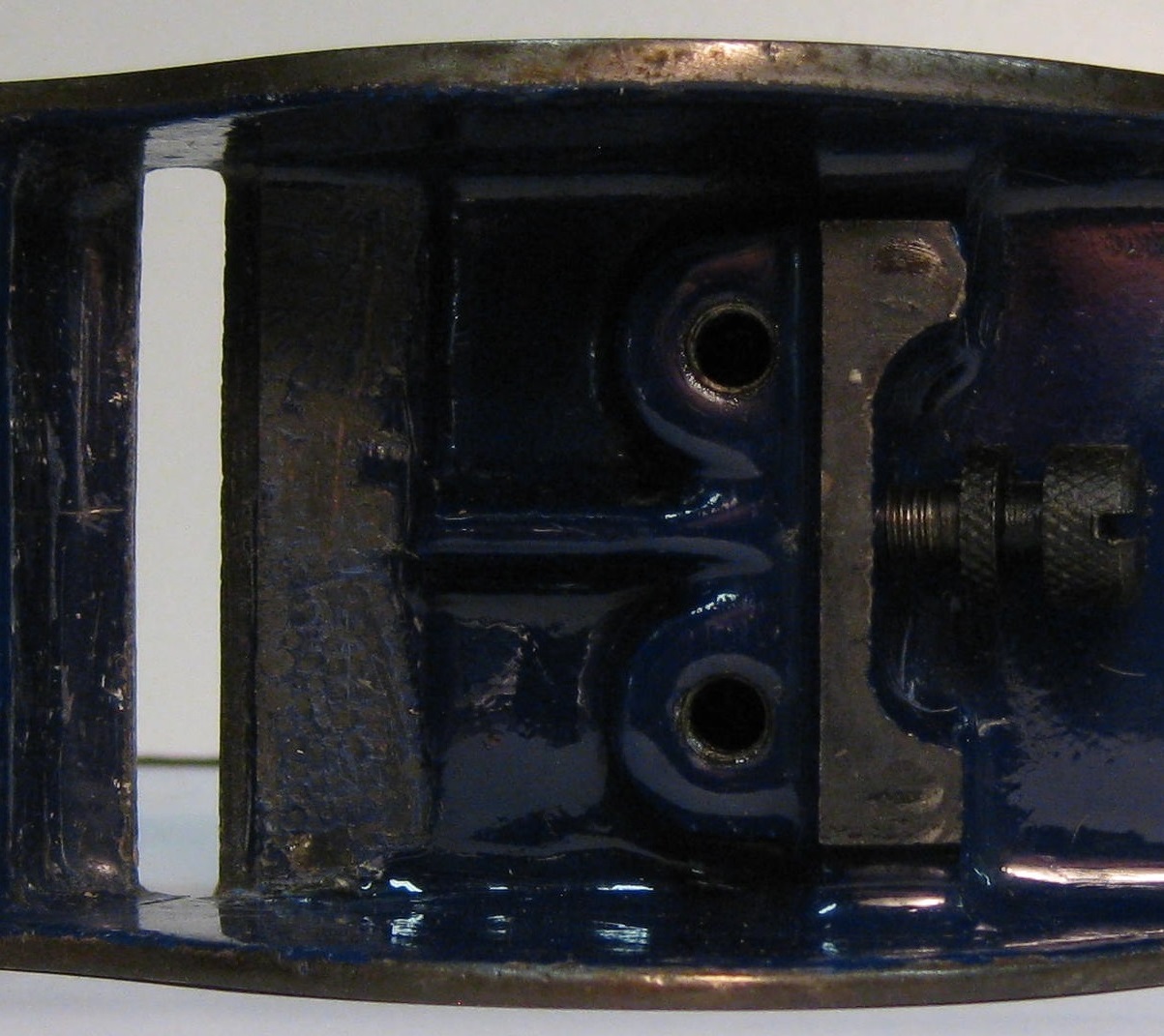
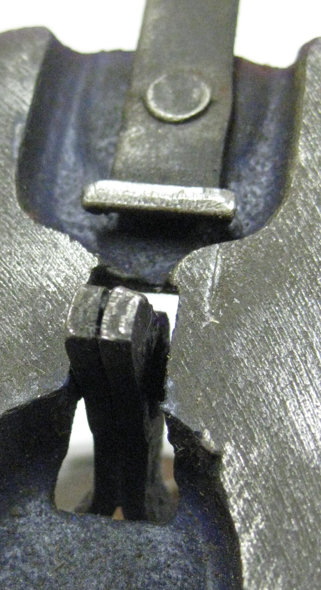
 STIRRUP
This is the mechanical communication between the circular Brass Depth Adjuster and the Cutter (Blade), and is, as the name suggests, shaped like a stirrup. Throughout production the stirrup was ALWAYS composed of 2 pieces of blackened, curved pressed steel, tightly joined by a hollow cylindrical brass rivet at the pivot point. (As opposed to the more usual one piece cast stirrup of other manufacturers.) The pivot steel rod was always inserted from the left [looking from the back] and this was done after the painting procedure, because an insertion line can usually be found across the frog at that area.
However RECORD, [and maybe other manufacturers] adopted this method in the late 60’s, so it was a very well conceived and financial decision by WS, [at that time in the forties], to adopt this method!
The photos below show the view from the back and from the front.

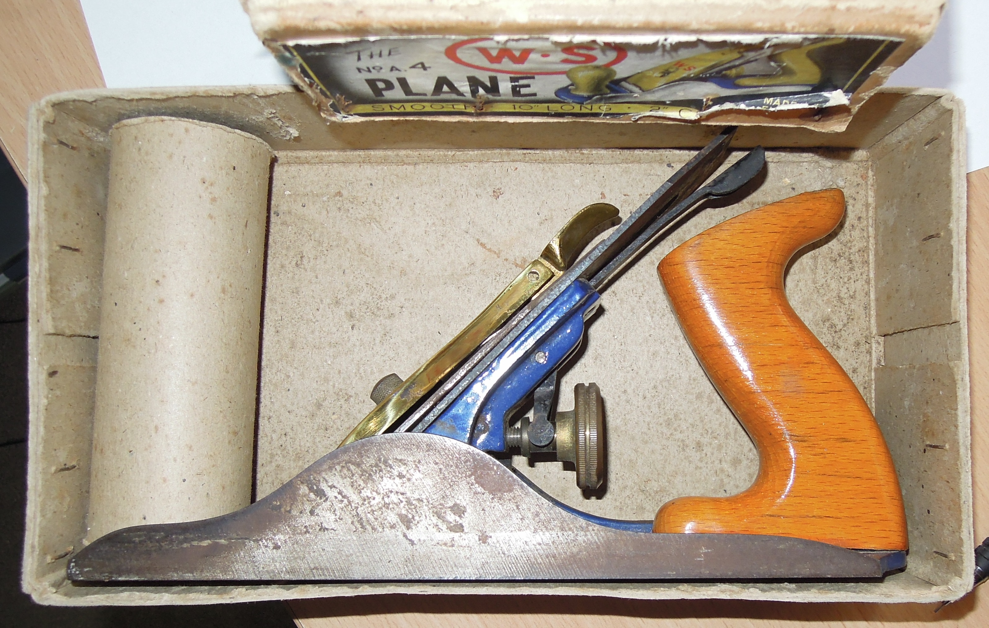
BOX and LABEL
The substantial box was made from a thick (1/16″+)(2mm) , non-corrugated cardboard, overlaid with brown paper and secured at each end by 4 staples (2 into each flap…see below). The label on boxes of No. 4 planes was always the same, showing the number as A4, even on planes that had base castings of just No. 4 and even after the change of brass lever cap style. So obviously the decision to change the base casting number was made to conform to the numbering of the next plane that was to be soon introduced (A5), and this enumeration decision must have been made very shortly after plane production commenced. Which begs the question….Why do we find so many planes of Type 1 and numbered just No. 4? ( if the decision to renumber was made so shortly after production commenced…as I have many Number 4 planes boxed with the A4 label… because was that very early decision made prior to label production?…which leads me back to the question of the number of No.4 planes made and found… am I repeating myself?) Did they literally flood the market with this initial offering? Obviously at that time it was not worthwhile to produce a more relevant label, and they never did!
The A4 box lid measures 15cm wide x 27cm long x 6.3cm deep
I am pleased that I can now offer to download to you (please provide an email address to ) a one page composite of printable colour labels accurately produced for direct printing for your WS A4 plane box labels. No Charge.
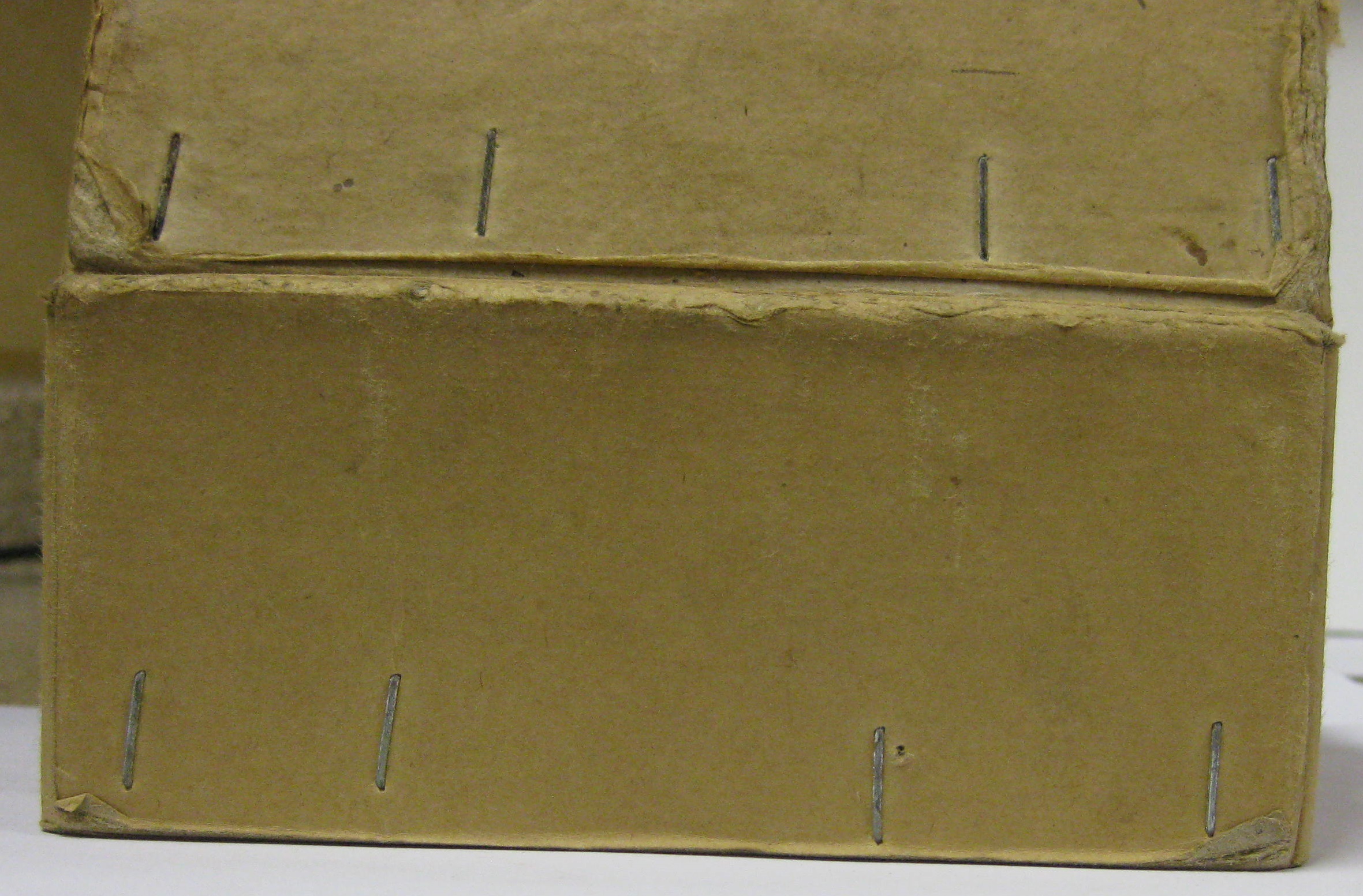
The above photo shows both the top and the bottom staple alignment.
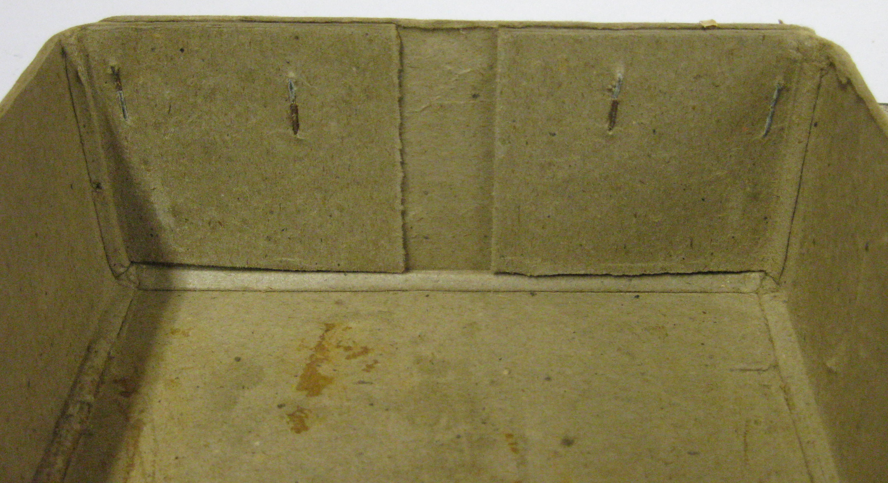
View from the inside
They must have had a special stapler that could staple in this fashion, as opposed to the usual stapling method which would be parallel to the long edge.
There have been 2 examples noted so far that the planes may well have been packed with a cardboard circular tube placed vertically over the front knob and of sufficient length to just touch the opposite side of the box. This would afford a great method to restrict movement of the plane during transit. Further examples are needed in order to confirm that this was standard procedure with WS, but I have never seen this with other manufacturers’ packing methods. Example below: